Electronic Basics The introductory chapter comprehensively and systematically introduces the functions, characteristics and detection methods of various commonly used electronic components.
1 Electronic basics – Ohm’s law
Add a voltage to the ends of a conductor, the electrons inside the conductor will be under the action of the electric field force for directional movement, forming an electric current. The direction of the current is specified as the opposite direction of the motion of the electrons (negative charge), i.e., the direction of the current is opposite to the direction of the motion of the electrons.
Figure 1-1 is a model of a circuit consisting of a battery, a switch, and a light bulb. When the switch is closed, the circuit forms a path, and the electromotive force of the battery forms a voltage, which then generates an electric field force, and the electrons within the electric field move in a directional motion under the action of the electric field force, which forms an electric current.
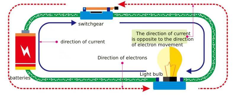
electronic component Figure 1-1 Model of a circuit consisting of a battery, a switch, and a light bulb
Voltage is also called potential difference (or potential difference) and is measured in volts (V). Current is able to flow in a circuit because of the presence of voltage in the circuit, which is the difference between a high potential and a low potential. The potential is the difference in magnitude between that point and a specified zero potential. The potential, also known as the electromotive force, is measured in volts (V) and is represented by the symbol “φ.” Its value is relative, and the magnitude of the potential at a given point in the circuit is related to the choice of reference point.
Resistance is the impedance of a substance to the current passing through it.
Ohm’s law defines the relationship between voltage (U), current (I) and resistance (R). In a circuit, the current flowing through a resistor is directly proportional to the voltage across the resistor and inversely proportional to the resistance, i.e., I = U/R, which is the basic concept of Ohm’s Law. Ohm’s law is one of the most basic laws in electronic basics circuits.
1.1 Effect of Voltage on Current
In the case of a circuit with constant resistance, the voltage across the resistor increases, and the current through the resistor increases proportionally; the voltage decreases, and the current through the resistor decreases proportionally.
Figure 1-2 shows the effect of voltage change on current. For example, when the voltage increases from 25V to 30V, the current value will also increase from 2.5A to 3A .
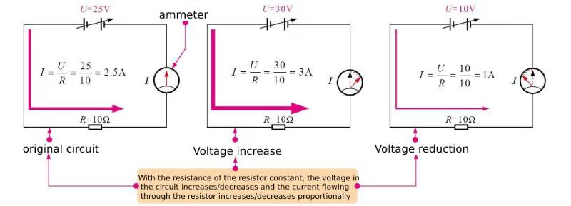
electronic component Figure 1-2 The effect of voltage change on current
1.2 Effect of resistance on current
In the case of a circuit with a constant voltage across the resistor, the current flowing through the resistor decreases proportionally as the resistor resistance rises; the current flowing through the resistor increases proportionally as the resistor resistance decreases.
Figure 1-3 shows the effect of resistance change on current. For example, if the resistance is raised from 10 Ω to 20 Ω, the current value decreases from 2.5 A to 1.25 A. The current value decreases when the resistance is raised.
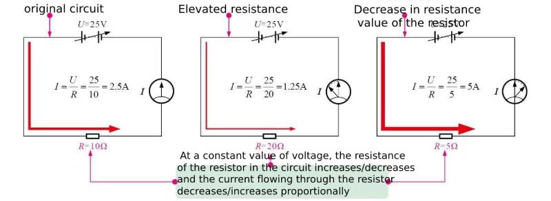
electronic component Figure 1-3 Effect of Resistance Change on Current
2 Electronic Basics – Electrical Power and Joule’s Law
2.1 Electric Work and Electric Power
2.1.1 Electric power
Energy is defined as the ability to do work. It exists in a variety of forms, including electrical, thermal, light, mechanical, chemical, and acoustic energy. Electrical energy is the energy carried by the movement of an electric charge.
The conversion of electrical energy takes place in the process of work done by an electric current. Therefore, the amount of electrical energy consumed by the current to do work can be measured in terms of electrical work. The formula for calculating electrical work is
W = UIt
where U is the voltage, V; I is the current, A; W is the electric work, J (Joule).
Daily production and life, electric power is also commonly used as a unit of degrees, home energy meter shown in Figure 1-4, is measured over a period of time in the family of all electrical appliances consume electricity (electric power) of the integrated. 1 degrees = 1kW – h = 1kV – A-h.
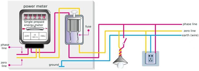
xuansn Capacitor Figure 1-4 Electricity Meter for Households
Electricity used in daily life comes mainly from the conversion of other forms of energy, including water energy (hydroelectric power), thermal energy (thermal power), atomic energy (atomic power), wind energy (wind power), chemical energy (batteries) and light energy (photovoltaic cells, solar cells, etc.). Electrical energy can also be converted into other desired forms of energy. It can be transmitted over long distances in wired or wireless form.
2.1.2 Electric power
Power is the rate at which work is done or energy is utilized. Electrical power is the work done by an electric current in potential time (seconds) and is identified by the letter “P”, i.e.
P = W/t = UIt/t = UI
where the unit of U is V, the unit of I is A, and the unit of P is W (watts). For example, Figure 1-5 shows an example of the calculation of electrical power.
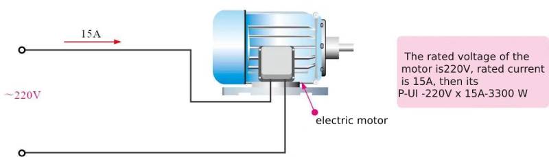
xuansn Capacitor Figure 1-5 Calculation example of electric power
Electric power is also commonly expressed in kilowatts (KW) and milliwatts (mW). For example, the power of an electrode is labeled as 2kW, which means that its power consumption is 2kW. It is also expressed in horsepower (a non-standard unit), and the relationship between them is:
1kW = 10 3W
W1mW = 10-3W
1 hp = 0.735 kW
According to Ohm’s law, the expression for electrical power can also be transformed into:
from P = W/t = UIt/t = UI, U = I R. Thus it can be obtained that
P = I2 R
from P = W/t = UIt/t = UI, I = U/R.Therefore, we have
P = U2 / R
From the above equation:
① When the current flowing through the load resistor is certain, the electric power is proportional to the value of resistance;
② when the voltage added to the load resistor on both sides of a certain voltage, electric power and resistance is inversely proportional to the value.
Most electrical equipment are labeled with wattage or power rating. Such as electric ovens labeled with 220V 1200W words, then 1200W for its rated electric power. Rated power that is the maximum electrical power of electrical equipment to work safely and normally. The maximum voltage of the normal operation of electrical equipment is called the rated voltage, such as AC 220V, that is, 220V AC power supply conditions. In the rated voltage of the electric power is called the rated power. The actual voltage added to the two ends of the electrical equipment is called the actual voltage, the actual voltage of the electric power is called the actual power. Only when the actual voltage is equal to the rated voltage, the actual power is equal to the rated power.
In a circuit, the rated power of the equipment actual power consumption is not necessarily large, should be determined by the actual voltage across the equipment and the actual current flowing through the equipment.
2.2 Joule’s Law
Handle near the incandescent light bulb lit for a period of time, you will feel the heat of the bulb; television, computer hosts and monitors, after a long period of time, the shell will heat, the phenomenon known as the thermal effect of electric current. That is: the conductor has a current through, the conductor will be hot, this phenomenon is called the thermal effect of the current.
We know that the light bulb and wire in series in the circuit, the same current, the light bulb heat, light, the wire is not very hot; the same wire if the light bulb into a high-power electric stove, the wire will be significantly hot, and even burned wire; iron energized for too long, but also produces a lot of heat, if you are not careful, it will be burned clothing. These all show that the heat generated by the current and the resistance of the conductor, the current and the time of energization.
British physicist Joule did a large number of experiments in 1840 was the first to determine the heat generated by the current with the current, resistance and energization time quantitative relationship: the current through the conductor of the heat generated by the current is proportional to the square of the conductor, with the conductor resistance is proportional to the energization time is proportional to the conductor resistance is proportional to the conductor resistance is proportional to the energization time is proportional to the heat generated by the conductor. This law is called Joule’s law.
With I for the current, R for the resistance, t for the energizing time, Q for the heat, Joule’s law can be expressed as follows
Q = I2 Rt
The thermal effect of electric current is widely used in production and life. For example, electric rice cookers, induction cookers, electric soldering irons, electric irons, electric heaters and so on, these electric heaters have the advantages of high thermal efficiency, easy to regulate the temperature, cleanliness and hygiene, which provide great convenience to production and life. However, the thermal effect of electric current also has unfavorable places, such as electric motors, televisions and other work will also have heat generation, which is a waste of electricity, but also may be burned when the machine is poor heat dissipation. In long-distance power transmission, due to the transmission line has resistance, inevitably make part of the power in the transmission line into heat and loss. Therefore, whether it is to utilize the thermal effect of electric current or to reduce the thermal effect of electric current, it is necessary to master the law about thermal effect.
3 Electronic Basics – Connectivity of Electronic Circuits
3.1 Series circuits
If more than one load in the circuit is connected to the first and last, then they are said to be connected in series, the circuit is called a series circuit.
Series circuits can be categorized into series connections of resistors, series connections of capacitors, and series connections of inductors.
3.1.1 Series connection of resistors
Two or more resistors in order to connect the first and last way is called series. Figure 1-6 shows a series circuit of resistors.
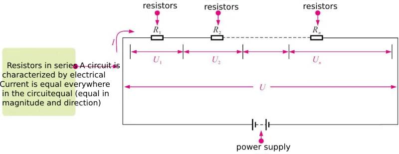
xuansn Capacitor Figure 1-6 Series Circuit of Resistors
If the resistor is connected in series to the poles of the power supply, then the current is equal everywhere in the circuit, and there is U1 =I R1 , U2 =I R2 , …, Un=I Rn , and U=U1+U2+…+Un, so there is U=I(R1+R2 +…+Rn), and thus the total resistance R after series connection is R = U/I=R1+R2+…+Rn, i.e. the total resistance after series connection is the sum of the resistances.
3.1.2 Series connection of capacitors
A capacitor is composed of two plates and has the function of storing electric charge. The amount of charge (Q) stored in a capacitor is directly proportional to the capacitance of the capacitor and the voltage applied to the two plates of the capacitor.
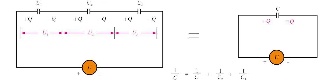
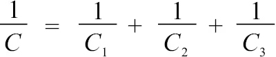
Figure 1-7 shows the circuit diagram and calculation method of three capacitors connected in series. The currents at all points in a series circuit are equal. When the external voltage is U, the voltages on each capacitor are U1, U2, and U3 respectively, and the sum of the voltages on the three capacitors is equal to the total voltage. The reciprocal of the combined capacitance of series capacitors is equal to the sum of the reciprocals of the capacitances of each capacitor.
Electronic basics
Figure 1-7 Circuit diagram and calculation method of three capacitors connected in series
If the charges on the capacitors are all the same value Q, then
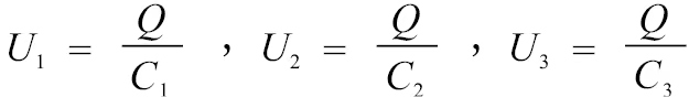
Electronic basics
Consider three capacitors connected in series as one capacitor C, then
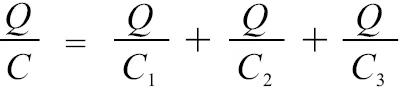
Electronic basics
Right now
Electronic basics
3.1.3 Series connection of inductors
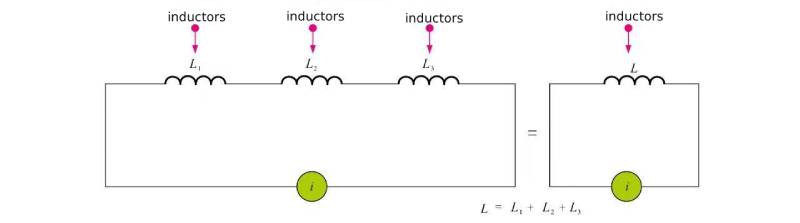
Figure 1-8 shows the circuit diagram and calculation method of three inductors connected in series. The currents in the series circuit are all equal, and the inductance is proportional to the number of turns of the coil.
Electronic basics
Figure 1-8 Circuit diagram and calculation method of three inductors connected in series
In an inductor series circuit, the calculation method of the total inductance is the same as the method of calculating the total resistance value of a resistor series circuit, that is, L=L1+L2+L3
3.2 Parallel circuit
When both ends of two or more loads are connected to the two poles of the power supply, the connection state is said to be in parallel, and the circuit is a parallel circuit.
According to the different types of circuit components, parallel circuits can be divided into parallel connections of resistors, parallel connections of capacitors, and parallel connections of inductors.
3.2.1 Parallel connection of resistors
The method of connecting two or more resistors (or loads) head to head and tail to tail is called a parallel connection of resistors. Figure 1-9 shows a parallel circuit of resistors. In a parallel circuit, the voltage across each parallel resistor is equal.
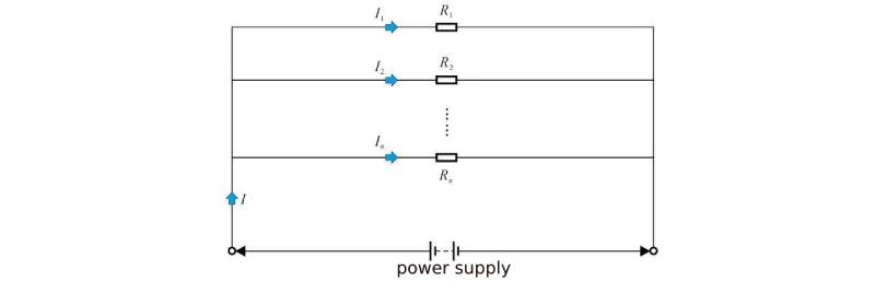
Electronic basics Figure 1-9 Parallel circuit of resistors
As can be seen from the figure, assuming that the parallel circuit is connected to the power supply, since the voltages at both ends of each parallel resistor in the parallel circuit are the same, according to Ohm’s law, I1=U/R1, I2=U/R2,…, In=U/Rn, And I=I1+I2+…+In, so there is
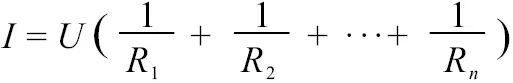
Electronic basics
The total resistance (R), voltage (U) and total current (I) of the circuit should also satisfy Ohm’s law, that is, I=U/R, so we can get
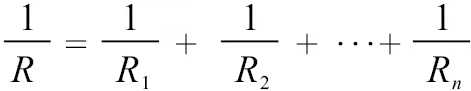
Electronic basics
Show that the reciprocal of the total resistance of a parallel circuit is equal to the sum of the reciprocals of the parallel branch resistances.
3.2.2 capacitors in parallel
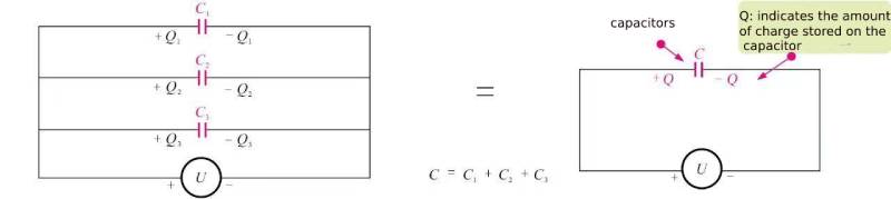
Figure 1-10 shows the circuit diagram and calculation method of three capacitors connected in parallel. The total current is equal to the sum of the currents of each branch. Apply voltage U to the three capacitors, and the charges stored on each capacitor are Q1=C1U, Q2=C2U and Q3=C3U respectively.
Electronic basics
Figure 1-10 Circuit diagram and calculation method of three capacitors connected in parallel
If the three capacitors C1, C2 and C3 are regarded as a capacitor C, then the charge of the combined capacitor Q = CU, and the charge of the combined capacitor is equal to the sum of the charges of each capacitor, that is
CU=C1 U+C2 U+C3 U=(C1+C2+C3)U
now that
C=C1+C2+C3
The resultant capacitance of parallel capacitors is equal to the sum of the three capacitances.
3.2.3 inductors in parallel
Figure 1-11 is a circuit diagram and calculation method of three inductors connected in parallel. The reciprocal of the parallel inductance is equal to the sum of the reciprocals of the three inductors, that is
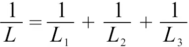
Electronic basics
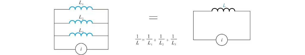
Electronic basics
Figure 1-11 Circuit diagram and calculation method of three inductors connected in parallel
3.3 Mixed circuit
In a circuit, a circuit that has both resistors in series and resistors in parallel is called a mixed circuit. The following two methods can be used to analyze mixed circuits.
3.2.1 Use the flow direction of current and the division and closing of current to decompose the circuit into partial series and parallel connections.
Figure 1-12 shows a mixed circuit of resistors. Analyze the circuit and calculate the equivalent resistance values at both ends A and B.
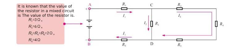
electronic component Figure 1-12 Mixed circuit of resistors
Suppose there is a power supply connected to both terminals A and B, terminal A is “+” and terminal B is “-“, then the current flows as shown by the arrow in the figure. In the I3 flow branch, R3, R4, and R5 are connected in series, so the total resistance R’CD of the branch is
Electronic basics
Since the branch where I3 is located and the branch where I2 is located are connected in parallel, so
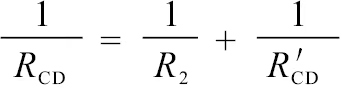
Electronic basics
now that
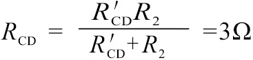
Electronic basics
R1, RCD and R6 are connected in series, so the total resistance of the circuit is RAB=R1+RCD+R6=10 Ω
3.2.2 Use the medium potential point of the circuit to analyze the mixed circuit
Figure 1-13 shows the analysis of a mixed circuit using the medium potential point of the circuit.
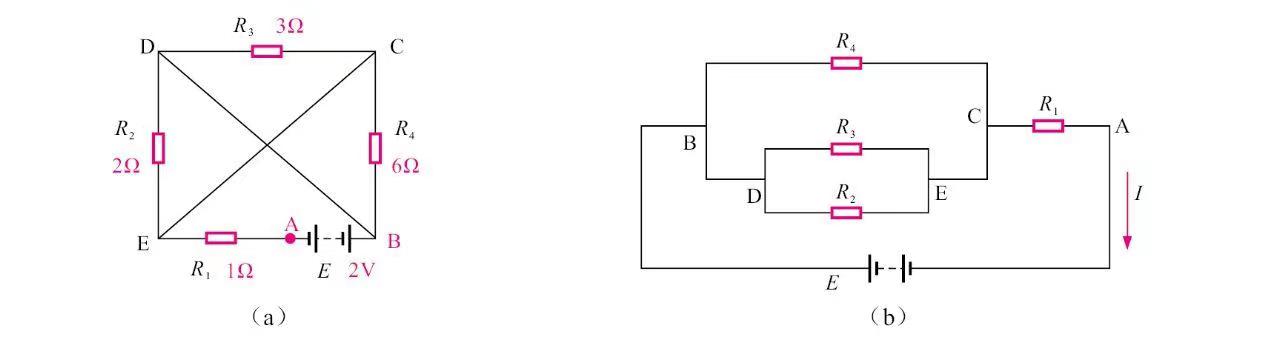
Electronic basics Figure 1-13 Use the medium potential point of the circuit to analyze the mixed circuit
Figure 1-13(b) is the equivalent circuit of Figure 1-13(a) drawn based on the equipotential points. As can be seen from the figure, R2, R3, R4 are connected in parallel and then in series with R1, so the total resistance RAB is
Electronic basics
The total current of the circuit is
Electronic basics
According to Ohm’s law, the voltage across R1 is U1=IR1=1×1=1V.
4 Electronics Basics – direct current and alternating current
4.1 DC and DC circuits
4.1.1 Direct current
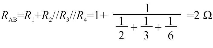
Direct Current (DC for short) means that the direction of the current does not change periodically with time, flowing from the positive electrode to the negative electrode, but the magnitude of the current may change.
DC can be divided into two types: pulsating DC and constant DC. As shown in Figure 1-14, the current in pulsating DC is unstable, while the current in constant DC is constant.

electronic component Figure 1-14 Pulsating DC and constant DC
Devices that can provide DC power are generally called DC power supplies, such as dry batteries, batteries, DC generators, etc. DC power supply has positive and negative poles. When a DC power supply supplies power to a circuit, the DC power supply can maintain a constant potential difference between the two ends of the circuit, thereby forming a current in the external circuit from the positive pole of the power supply to the negative pole, as shown in Figure 1-15.
electronic component Figure 1-15 Characteristics of direct current
4.1.2 DC circuit
The circuit powered by a DC power supply is called a DC circuit, which is mainly a closed circuit composed of a DC power supply and a load.
Battery-powered electrical appliances in life and production all belong to the DC power supply method, such as low-voltage low-power lighting lamps, DC motors, etc. There are also many electrical appliances that use AC-DC converters to convert AC into DC and then power the electrical products. Figure 1-16 shows the DC motor drive circuit, which uses a DC power supply. This is a typical DC circuit.
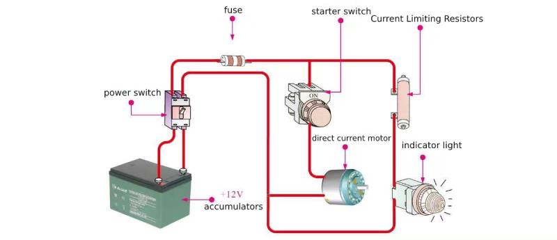
electronic component Figure 1-16 DC motor drive circuit
The power supply for households, enterprises and institutions all adopts AC 220V, 50 Hz power supply, and the circuit units and components inside electronic products often require a variety of DC voltages, so some circuits are needed to convert the AC 220V voltage into DC voltage to power the system. used on all parts of the road.
As shown in Figure 1-17, it can be seen from the figure that the AC 220V voltage first becomes AC low voltage (12V) through the transformer T. After being rectified by the rectifier diode VD, it becomes a pulsating DC, and the pulsating DC becomes a stable DC voltage after being filtered by LC.
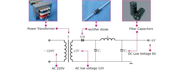
electronic component Figure 1-17 DC power supply circuit
4.2 AC power and AC circuits
4.2.1 Alternating current
Alternating Current (AC) refers to a voltage or current whose magnitude and direction change periodically over time. In daily life, all electrical products require a power supply to work properly. Most electrical equipment is powered by AC 220V, 50Hz. This is the unified standard for public electricity in our country. AC 220V voltage refers to The phase line is the voltage between the live line and the neutral line.
As shown in Figure 1-18, alternating current is generated by an alternator. There are usually models that produce single-phase alternating current and models that produce three-phase alternating current.
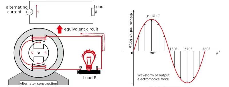
electronic component Figure 1-18 Generation of alternating current
4.2.1.1 Single-phase alternating current
Single-phase alternating current has a single alternating voltage in the circuit, which changes with time at a certain frequency, as shown in Figure 1-19. In a single-phase alternator, there is only one coil wound on the iron core to form the stator, and the rotor is a permanent magnet. When the stator and coil inside it are a group, the induced electromotive force (voltage) it generates is also a group. (phase), transmitted by two wires.
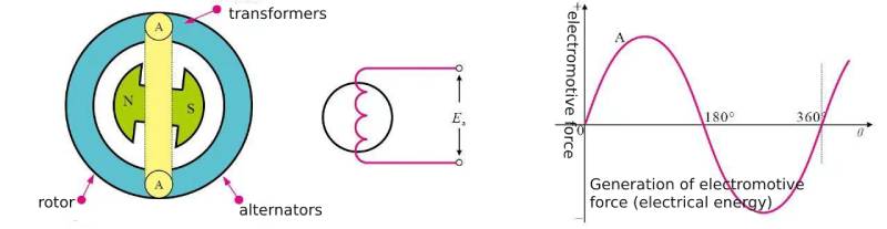
electronic component Figure 1-19 Generation of single-phase alternating current
4.2.1.2 Two-phase alternating current
There are two sets of stator coils in the generator distributed vertically around the rotor, as shown in Figure 1-20. When the rotor rotates, two sets of stator coils generate two sets of induced electromotive force. There is a 90° phase difference between the two sets of electromotive force. This power supply is a two-phase power supply. This method is mostly used in automation equipment.
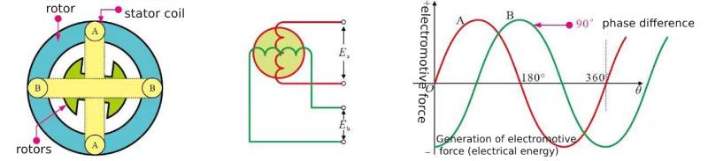
Electronic basics Figure 1-20 Generation of two-phase alternating current
4.2.1.3 Three-phase alternating current
Three-phase alternating current is generated by a three-phase alternator. Three stator windings A, B, and C with the same structure are placed in the stator slot. These windings are spaced 120° apart from each other. When the rotor rotates, its magnetic field changes sinusoidally in space. When the rotor is driven by a water turbine or a steam turbine to rotate clockwise at a constant angular speed ω, the three stator windings will have the same frequency, equal amplitude, and mutual phase. Three sinusoidal electromotive forces with a difference of 120° are symmetrical three-phase electromotive forces, as shown in Figure 1-21.
xuansn Capacitor Figure 1-21 Generation of three-phase alternating current
4.2.2 AC circuit
We call the circuit through which alternating current flows an alternating current circuit. AC circuits are commonly used in people’s daily life and production. Here we will introduce single-phase AC circuits and three-phase AC circuits respectively.
4.2.2.1 Single-phase AC circuit
The power supply methods of single-phase AC circuits mainly include single-phase two-wire power supply and single-phase three-wire power supply. Generally, household power supplies are single-phase AC circuits.
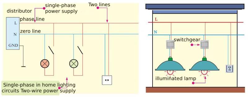
①Single-phase two-wire type – Single-phase two-wire type means that the power supply and distribution line only consists of one phase line (L) and one neutral line (N). The 220 V single-phase voltage is obtained through these two lines and distributed. To each electrical equipment.
Figure 1-22 shows the application of a single-phase two-wire AC circuit in home lighting.

xuansn Capacitor Figure 1-22 Application of single-phase two-wire AC circuit in home lighting
②Single-phase three-wire type – The single-phase three-wire type adds a ground wire to the single-phase two-wire type, which is composed of a phase line, neutral line and ground wire. Among them, the voltage between the ground wire and the phase wire is 220 V, and the voltage between the neutral wire (neutral wire N) and the phase wire (L) is 220 V. Since there is a certain potential difference between different grounding points, there may be a certain voltage between the neutral line and the ground line.
Figure 1-23 shows the application of a single-phase three-wire AC circuit in home lighting.
xuansn Capacitor Figure 1-23 Application of single-phase three-wire AC circuit in home lighting
4.2.2.2 Three-phase AC circuit
There are three main power supply methods for three-phase AC circuits: three-phase three-wire, three-phase four-wire, and three-phase five-wire. Generally, electrical equipment in factories often use three-phase AC circuits.
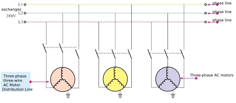
① Three-phase three-wire type – Three-phase three-wire AC circuit means that the power supply line is composed of three phase wires. The voltage between each phase wire is 380V. Electrical equipment with a rated voltage of 380V can be directly connected to the phase wires, as shown in the figure As shown in 1-24. This power supply method is mostly used in electric energy transmission systems.
xuansn Capacitor Figure 1-24 Three-phase three-wire AC circuit
②Three-phase four-wire type – Three-phase four-wire AC circuit refers to the power supply method in which four wires are drawn out from a transformer. Three of them are phase wires, and the other neutral wire is the neutral wire. The neutral line is connected to the midpoint of the three-phase winding of the motor. When the electrical equipment is connected to the neutral line, the current will do work through the electrical equipment. The current without work can return to the power plant through the neutral line, thus protecting the electrical equipment. This power supply method is often used for 380/220V low-voltage power and lighting hybrid power distribution, as shown in Figure 1-25.
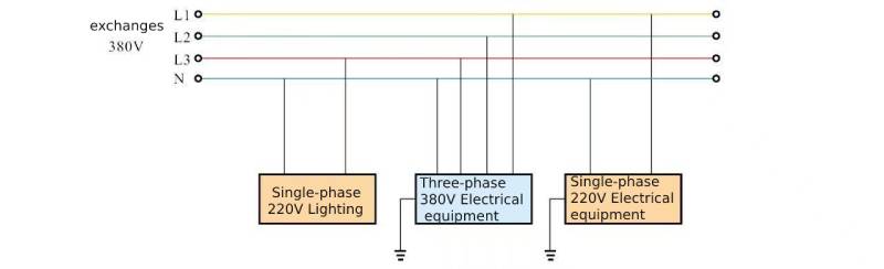
xuansn Capacitor Figure 1-25 Three-phase four-wire AC circuit
Note: In the three-phase four-wire power supply mode, when the three-phase load is unbalanced and the neutral line of the low-voltage power grid is too long and the impedance is too large, zero-sequence current will flow through the neutral line. If the low-voltage power grid is too long, due to the environment Due to factors such as deterioration, wire aging, moisture, etc., the leakage current of the wire forms a closed loop through the neutral line, causing the neutral line to also carry a certain potential, which is very detrimental to safe operation. In the special case of the neutral wire being disconnected, the single-phase equipment and all the equipment connected to the neutral line after the disconnection will generate dangerous voltages, which is not allowed.
③Three-phase five-wire type – Figure 1-26 is a schematic diagram of a typical three-phase five-wire power supply method. In the three-phase four-wire AC circuit mentioned above, the two functions of the neutral line are separated, that is, one line is used as the working neutral line (N), and the other line is used as the protective neutral line (PN). Such power supply The wiring method is called a three-phase five-wire AC circuit.
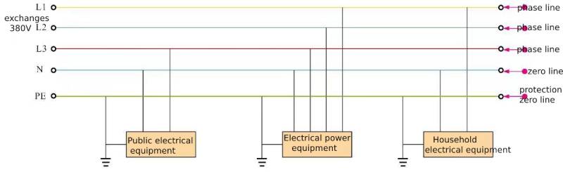
xuansn Capacitor Figure 1-26 Three-phase five-wire AC circuit
In a three-phase five-wire AC circuit, the working neutral line N and the protective neutral line PE connected to the electrical equipment are laid separately. The potential on the working neutral line cannot be transmitted to the shell of the electrical equipment, so that It effectively isolates the dangerous voltage caused by the three-phase four-wire power supply method. The potential on the shell of the electrical equipment is always at the “ground” potential, thus eliminating the hidden danger of dangerous voltage generated by the equipment.
