1.1 Basic knowledge of capacitors – what is capacitance
Basic knowledge of capacitors– What is capacitance? As the name suggests, it is the ability to hold electricity. Some books describe it like this: “For any ‘isolated’ conductor that is not affected by the outside world, when the conductor is charged, the amount of electricity q carried by the conductor and the corresponding potential U The ratio C is a physical quantity that has nothing to do with the electric charge carried by the conductor, and is called the capacitance of the ‘isolated’ conductor”, that is
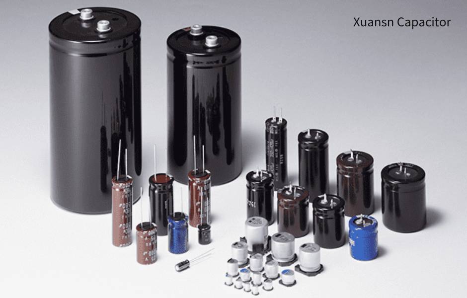
Xuansn capacitor
The capacitance of a conductor represents the unique properties of the conductor and refers to the electric charge carried by the conductor when the reference potential at infinity is “one” unit.
In the SI unit, the unit of capacitance is farad [farad]. If the charge carried by the conductor is 1C and the corresponding potential is 1V, the capacitance of the conductor is 1 farad, that is, 1 F. If you think the unit F is too big, you can also use smaller units such as mF, μF, nF, pF, etc. Their mutual relationship is

The dimension of the capacitor is I2L-2M-1T4
1.2 What is a capacitor
What is a capacitor? As the name suggests, it is a device that holds charges. When there are other objects around a conductor, the capacitance of the conductor will be affected. Therefore, it is necessary to design a conductor combination that has a large capacitance value but a small geometric size and is not affected by other objects. Such a combination of conductors is a capacitor. In physics, the concept of a capacitor can be expressed as: a conductor system composed of two conductors when there are no other charged conductors around. The capacitance (or capacitance) of a capacitor is defined as the ratio of the electric charge q to the corresponding potential difference UA-UB between the two plates when the two plates of the capacitor carry equal and different charges q, that is,
Basic knowledge of capacitors
An isolated conductor can actually still be considered a capacitor, but the other conductor is at infinite distance and the potential is zero, so equation (1-3) becomes equation (1-1). Therefore, the capacitance of an isolated conductor is actually the capacitance between two conductors. But capacitance is a characteristic between conductors after all, and the capacitance of an isolated conductor does not actually exist.
1.3 Basic knowledge of capacitors – the physical meaning of capacitors
1.3.1 The physical meaning of capacitors in the time domain

If the current changes, then equation (1-4) should be written as:

Basic knowledge of capacitors
In general applications, the potential difference between the two plates of the capacitor is the voltage on the capacitor, expressed as UC. From equation (1-4) and equation (1-5), the relationship between capacitor voltage and current is:

Capacitor energy storage

The unit of A is J
1.3.2 The physical meaning of capacitors in the frequency domain
When the voltage is a sine wave signal, equation (1-6) becomes

Solve the integral to get

In the formula, UC, IC, and ω are voltage amplitude, current amplitude, and angular frequency respectively, and voltage amplitude and current amplitude are both scalars.
It can be seen from equation (1-9) that after the sine wave voltage is applied to the capacitor and enters a steady state, the current flowing through the capacitor leads the capacitor terminal voltage by 90°.
Arrange the formula (1-9) to get
Xuansn capacitor
Obviously, equation (1-10) is very similar to Ohm’s law, which means that the capacitor behaves like a resistor in the circuit when excited by a sine wave voltage. But since the voltage and current of the capacitor are 90° out of phase, there is no power loss in the capacitor. The ratio of capacitor voltage to current can be called capacitive reactance. Since there is a 90° phase difference between the voltage and current of the capacitor, for the convenience of circuit analysis, in the frequency domain analysis, the capacitive reactance of the capacitor is an imaginary number, and it is a negative imaginary number. Therefore, equation (1-10) can be simplified to

Then equation (1-11) is more like Ohm’s law.
From equation (1-11), we can see that when the frequency and capacitance remain unchanged, the voltage is proportional to the current; when the frequency and voltage remain unchanged, the capacitance is proportional to the current. These two laws are very similar to Ohm’s law. When the capacitance and voltage remain unchanged, the current is inversely proportional to the frequency, indicating that the capacitive reactance of the capacitor decreases as the frequency increases.
The significance of the capacitor frequency is that it can form series resonance or parallel resonance with the inductor to obtain excellent frequency selection characteristics, so that the non-sinusoidal voltage or current can pass through the resonant circuit composed of the capacitor and the inductor to obtain a sine wave voltage or sine wave on the load. Wave current, such as induction heating, radio frequency power amplifier, etc. This is very important in the field of electrical engineering and electronic technology. Capacitors and resistors can form a phase shift circuit, so that when the sine wave voltage passes through the capacitor-resistance circuit, the phase and amplitude of the input voltage and output voltage change. When a non-sinusoidal voltage passes through a circuit composed of capacitors and resistors, the waveform will change, and the required voltage waveform or time delay can be obtained.
1.4 Capacitance of plate capacitor
Isolated capacitors in physics have almost no practical applications. Practical applications are capacitors with two electrodes, usually approximated by “plate capacitors”. The capacitance formula of a plate capacitor is shown in Equation (2-1).
In order to obtain the largest possible electrode area, aluminum electrolytic capacitors use etched foil, and tantalum electrolytic capacitors use porous tantalum blocks. Since the aluminum oxide dielectric layer can be accurately obtained electrochemically, the aluminum oxide film can be made very thin, which is equivalent to the electrode plates being very close together.
Due to the high dielectric coefficient, large plate area, and very close distance, aluminum electrolytic capacitors and tantalum electrolytic capacitors have relatively small sizes.
1.5 Single-phase rectification and filtering requires large capacitance capacitors
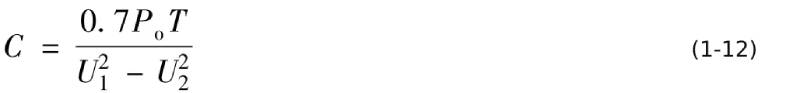
One of the main applications of capacitors is to smooth pulsating DC power into smooth DC power during the power frequency rectification process (this process can also be called filtering). For example, when converting sinusoidal alternating current into direct current, the smooth rectified direct current requires capacitor filtering to “short-circuit” the AC component in the pulsating direct current with a capacitor. However, smoothing the pulsating voltage from zero to peak value (1.414 times the effective value) into a nearly smooth DC voltage requires a capacitor with a large capacitance. For example, how much capacitance is needed to smooth the single-phase bridge rectifier output voltage to only a 10% fluctuation? What about the capacitor? Take the single-phase bridge rectifier as an example: In a capacitor input filter circuit, each rectifier diode generally conducts for only about 3 ms to supply power to the output, and the output is powered by the filter capacitor for about 7 ms. At this time The energy storage of the capacitor will fluctuate by about 20%, that is, the capacitor provides 20% of the energy storage to the output for each half power cycle, corresponding to 70% of the output power. According to the law of conservation of energy, the energy that the rectifier filter capacitor needs to provide at half a power supply cycle of 50Hz is:
In the formula, U1 and U2 are the peak voltage and valley voltage of the rectifier and filter capacitor respectively. The required capacitance is
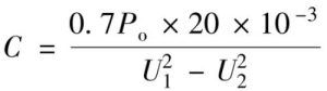
When the frequency f=50Hz, the power cycle is 20ms, and the required capacitance is
For example, under the condition of AC 220V (1-20%), that is, 220V power supply is at the lowest input voltage, corresponding to AC 176V, the peak point voltage of the direct rectified output voltage is approximately 230V, and the valley point voltage of the rectified output voltage is 190V to supply power to a 100W load. For example, the required capacitance is
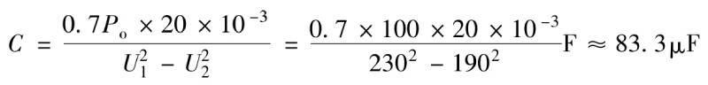
About 83μF, the size and price of an 83μF/400V film capacitor are difficult to accept.
For another example, the capacitance required for a rectifier that supplies power to 15V/1A (the peak voltage and valley voltage of the rectifier before the voltage stabilizing circuit are 25V and 20V respectively) is
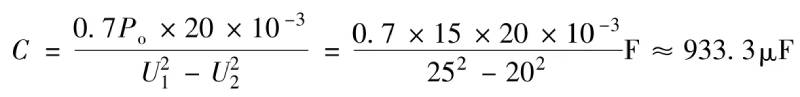
About 1000µF, a 1000µF/25V film capacitor would not be tolerated!
For the above reasons, it is necessary to seek a capacitor with large capacitance, small size and low price. In the first half of the 20th century, when capacitor manufacturing technology was not very advanced, if we wanted to obtain high-capacity capacitors, film capacitors and ceramic capacitors would be extremely expensive and could not be put into use, so we had to find another way out.
People naturally think of ways to increase the surface area of the capacitor plate, such as roughening the surface of the plate or making the plate as porous as a sponge. The next question is, when one plate becomes rough or porous, how to make the other plate in close contact with it, and also sandwich a dielectric material of uniform thickness and texture in the middle. These technical requirements are almost impossible for ordinary film capacitors and ceramic capacitors. Therefore, it is necessary to seek a medium and electrode form that adapt to this requirement. Electrolytic capacitors emerged under this technical demand and market demand.
1.6 Low frequency power electronic circuit power supply bypass requires large-capacity capacitors
The audio power amplifier needs to work between 20Hz and 20kHz. In order to maximize efficiency, most audio power amplifiers operate close to Class B amplifiers. Therefore, the current that the audio power amplifier draws from the DC power supply is a DC pulsating current with an audio output current component. It should be noted that the DC power supply cannot provide an AC current component to the load due to its own parasitic inductance. This AC current component can only be provided by the DC bypass capacitor of the audio power amplifier to avoid the voltage of the DC power supply caused by the AC current component of the load. The change range exceeds the allowed value.
The output current of the audio power amplifier, the current requested from the DC power supply, and the current waveform of the bypass capacitor are shown in Figure 1-1.
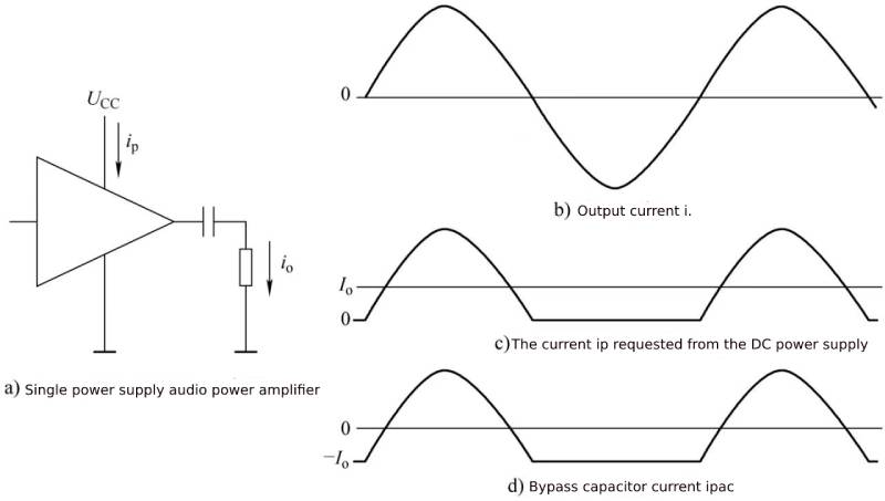
It should be noted that the negative half cycle of the output current of a single power supply audio power amplifier is not powered by the DC power supply, but is provided by the output coupling capacitor, so the current the audio power amplifier requires from the DC power supply is only a sinusoidal half wave.
If it is powered by dual power supplies, the currents provided by the positive and negative power supplies are the same as in Figure 1-1, except that when the audio power amplifier outputs a positive half-cycle current, the positive power supply provides the output current, and when it outputs a negative half-cycle current, the negative power supply provides the output current. .
If it is a push-pull audio power amplifier, the DC power supply provides the amplifier output current regardless of the positive half cycle or the negative half cycle of the amplifier output. At this time, the current required by the amplifier is the absolute value of the sine wave.
As a bypass capacitor, the AC impedance in its operating frequency range is at least lower than 1/10, or even 1/100, of the output load impedance.
It is also an audio power amplifier. If the load impedance is 8Ω, the impedance of the bypass capacitor should be 0.8Ω or even 0.08Ω. If the output frequency is 20Hz, the capacitive reactance of the bypass capacitor at 20Hz should be 0.8Ω or even 0.08Ω.
From the capacitive reactance XC=1/2πfC of the capacitor, it is deduced that the required capacitance is
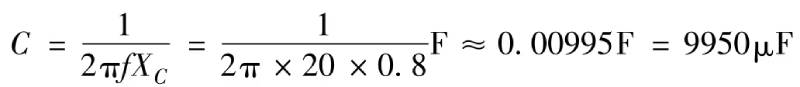
Obviously, this is a very large capacitance. If you choose a film capacitor, it will be huge and extremely expensive. Ceramic capacitors cannot achieve such a high capacitance. Only aluminum electrolytic capacitors can meet the requirements.
From this case, we can see the basic knowledge of capacitors – for low-frequency bypass, when a capacitance of more than 10μF is required, electrolytic capacitors need to be considered.
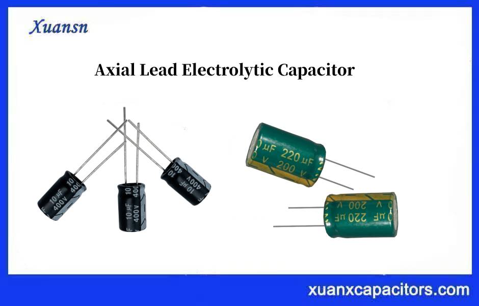
If you need to know more about electrolytic capacitor products, please click:http://xuansncapacitor.com

