1.Analysis of the working state of capacitors – Proposing the problem of power factor correction
Analysis of the working state of capacitors — single-phase rectifiers and filter capacitors are directly combined into a rectifier and filter circuit, which is the simplest solution for converting alternating current into direct current. The problem caused by this solution is that due to the direct combination of the nonlinear characteristics of the rectifier and the energy storage characteristics of the energy storage element, the AC input current of the rectifier becomes a non-sinusoidal pulse current waveform, resulting in an obvious power factor of the rectifier filter circuit. dropped, even below 0.7.
The input current waveform of the most common single-phase bridge rectifier circuit is shown in Figure 1-1, and the harmonic analysis of the input current is shown in Figure 1-2.
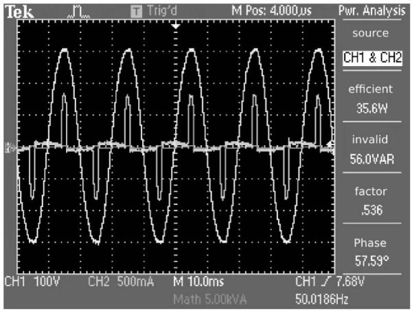 Figure 1-1 Input current waveform of single-phase format rectifier circuit
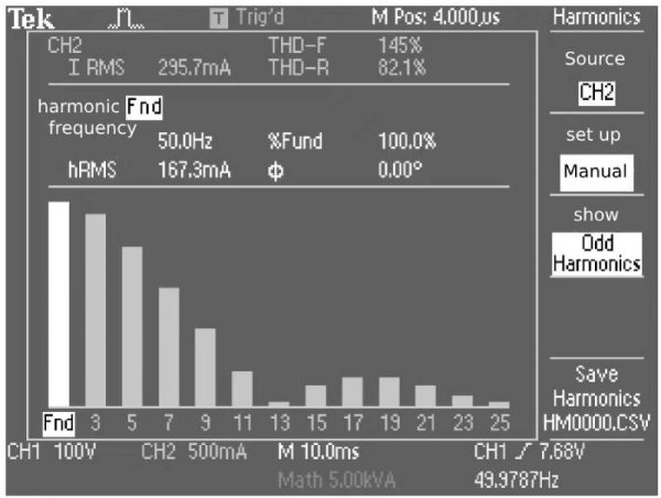 Figure 1-2 Harmonic analysis of input current
Through Fourier series expansion, each harmonic is obtained, see Table 1-1.
Table 1-1 Input current harmonic components directly filtered by single-phase bridge rectifier capacitor

The current AC power grid is a sine wave voltage power supply mode, which is based on vector analysis. Its basic requirement is that both voltage and current are sine waves.
Another major advantage of sine wave AC power is that when any linear circuit is connected to a sine wave AC power grid, all branch voltages and currents are sine waves. Compared with the sine wave AC voltage at the input end, there are only changes in amplitude and phase.
After non-sinusoidal alternating current passes through a linear network, its output voltage and current may no longer be sinusoidal. This is undoubtedly a disaster for power supply and electricity consumption. Therefore, the sine wave voltage power supply method of the AC power grid and the load sine wave current power consumption method are the most harmonious power supply and power consumption methods.
With the advent of power electronic circuits, such as early mercury rectifiers and gas-filled thyristor rectifiers, non-sinusoidal load currents were produced.
With the advent of power semiconductor devices, especially thyristors and thyristor circuits, higher harmonic currents are generated that are much larger than those produced by mercury rectifiers and gas-filled thyristor circuits, which directly affects the power supply quality of the AC power grid.
With the extensive application of switching power supplies, the bridge rectifier and capacitor filter circuits in them generate higher harmonic currents that are much larger than those of thyristor circuits of the same power, resulting in poor quality of low-voltage AC power supply.
Based on the above reasons, the European Union proposed the issue of high-order harmonic current limits in 1996, which resulted in the issue of power factor correction. Power factor correction completely solves the current problem of non-linear loads. The power factor correction circuit is actually a boost converter in DC/DC.
Analysis of the working state of capacitors— the above is the analysis of the power factor correction problem
2.Analysis of the working state of capacitors—The contradiction and fusion between the changing input power function and the smooth output power function
When the rectifier circuit has a power factor correction function, the input current of the rectifier must be a “sinusoidal” AC current of the same frequency and phase as the AC power supply voltage, and the corresponding input power is
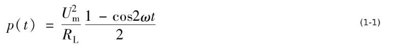
In the formula, Um is the peak value of AC power supply voltage; RL is the load resistance.
It can be seen from equation (1-1) that the power variation pattern with time when single-phase sinusoidal alternating current supplies power to a linear load is the algebraic superposition of a constant and a cosine function with 2 times the frequency, as shown in Figure 1-3. In the figure, Po is the average value of the power function, and po is the instantaneous value of the power function.

Figure 1-3 The power changes with time when single-phase sinusoidal alternating current supplies power to a linear load
Such a power function cannot be used for DC loads. Therefore, the single-phase power factor correction circuit should output smooth output power, that is, the output power function of power factor correction should be a constant value.
According to the law of conservation of energy, energy must be conserved at any time, and the corresponding instantaneous power must also be conserved. Therefore, a contradiction in energy conservation arises between changing input power and constant output power. In order to resolve this contradiction, a buffer between changing energy and constant energy must be provided at the power factor correction output end. This buffer element in the circuit It is the energy storage component. The most convenient application is the capacitor, that is, the filter capacitor at the power factor correction output end. The working state of this filter capacitor changes from the current flowing through the rectifier filter capacitor to be dominated by 100Hz ripple current and high-order harmonic current above 100Hz to the high-frequency switching pulse current of the power factor correction circuit. So, how to analyze the working status of the filter capacitor at the power factor correction output? It is necessary to understand the circuit topology of the power factor correction current and the working status of the output current.
Analysis of the working status of the capacitors—The above is the contradiction and fusion analysis between the changing input power function and the stable output power function.
3.Analysis of the working state of capacitors—Analysis of the working status of the most commonly used boost power factor correction circuit
The boost single-phase power factor correction circuit is shown in Figure 1-4.
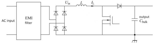 Figure 1-4 Boost single-phase power factor correction circuit
In Figure 1-4, the EMI filter is the power supply filter, IL is the inductor current, and Uin is the rectifier output voltage.
As can be seen from Figure 1-4, the boost single-phase power factor correction circuit can be roughly divided into three parts: rectifier circuit, power factor correction circuit, and output filter capacitor circuit.
The power factor correction circuit (before the filter capacitor) has no energy storage component. According to the law of conservation of energy, the input power of the rectifier circuit is equal to the output power of the power factor correction. Since the input voltage is a sine wave, and power factor correction requires the input current to be a sine wave with the same frequency and phase as the input voltage, the input power function is formula (1-1), then the output power function of the power factor correction circuit is also a DC component. The superposition of the sine function with 2 times the power frequency, that is
As for the power factor corrected output DC voltage, the corresponding output current change rule should be the second half of equation (1-2). In this case, equation (1-2) can be written as

The current function in equation (1-3) changes in the same way as in Figure 1-1. The function of the filter capacitor is to introduce the AC current component in equation (1-3) into the capacitor to prevent the AC current component from flowing into the load of the power factor correction circuit.
Equation (1-3) only reflects the power conversion relationship at the AC power frequency or 2 times the frequency. To realize this changing relationship, high-frequency switching control is required. At this time, the filter capacitor also flows through the AC current at the switching frequency. Portion, and the main part.
The next question is how to analyze the current flowing through the filter capacitor. The filter capacitor voltage is not analyzed here because the power factor correction output voltage can be considered a constant DC voltage, as long as the filter capacitor withstand voltage is higher than the actual voltage of the power factor correction output.
Analysis of the working state of capacitors—The above is an analysis of the working status of the most commonly used boost power factor correction circuit.
4.Analysis of the working state of capacitors—minimum capacitance
The capacitance required to ensure the normal operation of the power factor correction circuit is the minimum capacitance. Below this capacitance, although the power factor can be guaranteed, the high-order harmonic current may increase to an unsatisfactory level.
Equation (1-3) shows that the output power of the power factor correction circuit is the DC component superimposed on the cosine function of 2 times the power frequency. Since the output of the power factor correction circuit is DC, the corresponding output current is the DC component superimposed on the cosine function of 2 times the power frequency.

Among them, the DC component is the output current of the power factor correction circuit, the AC component is the current flowing into the filter capacitor, and the current flowing into the filter capacitor is

The output current, filter capacitor current and output voltage waveforms of the power factor correction circuit are shown in Figure 1-5.
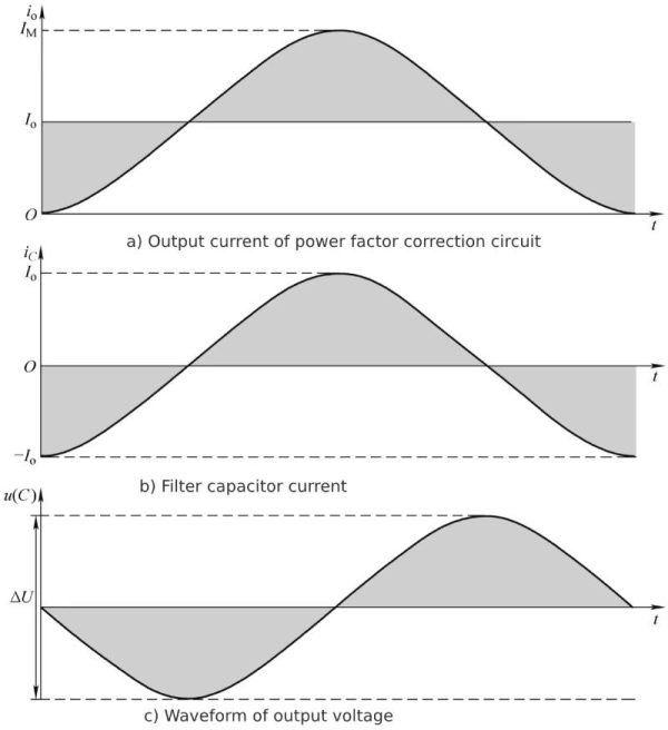 Figure 1-5 Current and output voltage waveforms
The frequency of the output AC current component of the power factor correction circuit of 50Hz sine wave AC is 100Hz, the corresponding angular frequency ω=2πf=628Hz, the period is 10ms, and the half period is 5ms. With this information, integrating equation (1-5) gives the generated charge as

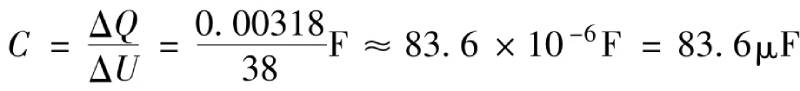
From formula (1-6), it can be seen that the average output current is 1A, and the charge flowing into the filter capacitor is 0.00318C (Iav=0.5IM).
Assume that the output voltage of the power factor correction circuit is 380V, the average output current is 1A, and the corresponding output power is 380W.
It can be known from Coulomb’s law
![]()
Changes in the output current of the power factor correction circuit cause changes in charge, and changes in charge produce changes in voltage.
![]()
If the output voltage changes by 10%, that is, changes by 38V, the corresponding minimum capacitance required is
The output power that can be provided by the corresponding unit capacitance is

It can be seen from equation (1-9) that when the output voltage fluctuates 38V, each microfarad can support 4.09W output power (taking into account that the efficiency of the subsequent stage converter is 90%). A simple calculation is that each microfarad can support 4W output power. If the output voltage fluctuates by 27V, it can support approximately 3W output power per microfarad.
Analysis of the working state of capacitors—the above is the analysis of the minimum capacitance
5.Analysis of the working state of capacitors—Analysis of support capacitor ripple current in current continuous mode
How can we know the effective value of the current flowing through the filter capacitor? Since the power factor correction circuit outputs current pulses and is pulse width modulated, it cannot be calculated using conventional mathematical methods.
The output function of the power factor correction circuit of Equation (1-3) is obtained through pulse width modulation, that is to say, each pulse is taken as its effective value (root mean square value), and a period of Equation (1-3) ( Or 1/2 cycle or 1/4 cycle) The effective value of each pulse is obtained by the root mean square method to obtain the actual effective current value of the filter capacitor.
For the convenience of analysis, it is assumed that the power factor correction circuit outputs a rectangular current pulse, as shown in Figure 1-6.
Figure 1-6 The upper picture shows the circuit output current pulse waveform, and the lower picture shows the smoothed current curve of the circuit output current pulse.
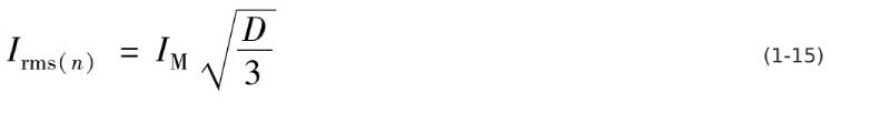
In Figure 1-6, the effective value of each pulse current is
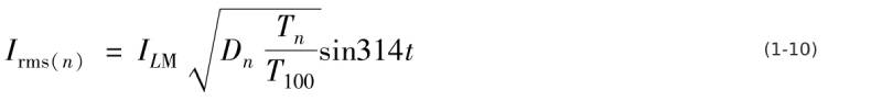
In the formula, Irms(n) is the effective value of the nth current pulse output by the power factor correction circuit in one switching cycle; ILM is the peak output current of the power factor correction circuit (inductor current peak); Dn is the output current of the power factor correction circuit. The duty cycle of the nth current pulse; Tn is the switching period of the nth current pulse of the power factor correction circuit; T100 is the 2 times frequency (or 100Hz) period of 50Hz.
The duty cycle Dn of the nth current pulse output by the power factor correction circuit is
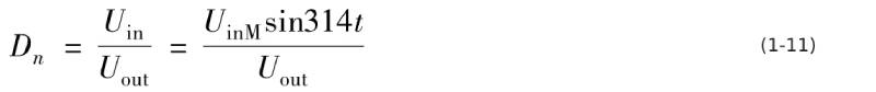
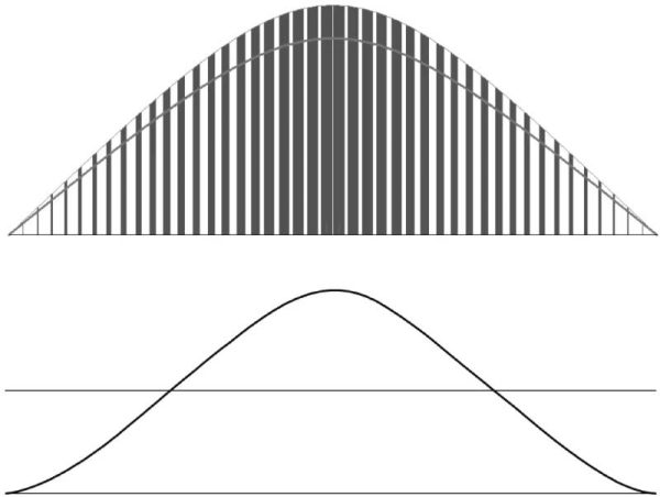 Figure 1-6 Power factor correction circuit output current pulse waveform
As can be seen from Figure 1-6, the amplitude of each current pulse is the highest amplitude of the circuit output multiplied by the duty cycle of this current pulse. The current pulse is multiplied by the square root of the duty cycle of a power cycle. The amplitude is the effective value of the current pulse.
Formula (1-10) The root mean square value of a period of current pulse in each power cycle is

The next question is how to calculate the effective value of the output current.
Analysis of the working state of capacitors—The above is the analysis of the ripple current of the support capacitor in the current continuous mode.
6.Analysis of the ripple current of the support capacitor in the current continuous mode using the international common voltage of 85~264V
6.1 Support capacitor current analysis
Under the international universal power supply voltage, the worst working state of the filter capacitor in the power factor correction circuit should be at 85Vac voltage. The worst working state was analyzed, and other working states can be satisfied.
Before calculating the effective value of the output current, it is necessary to determine the output voltage of the power factor correction circuit to determine the conduction duty cycle of the switching tube in the power factor correction circuit. It is assumed here that the output voltage is 400V and the average output current is 1.
First analyze the output current of power factor correction in current continuous mode.
When the effective value of the AC power supply voltage is 85V, the corresponding peak voltage is 120V. According to the relationship between the input and output voltages of the boost converter, the minimum duty cycle of the switching tube can be obtained.
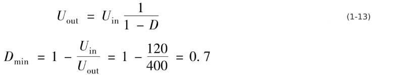
The maximum duty cycle of the diode conduction is
Ddmax=1-Dmin=1-0.7=0.3
At this duty cycle, the peak output current ILM of the power factor correction circuit is 3.333 (reciprocal of 0.3) times the “smooth” output current, and the average output current of the power factor correction circuit is 1/2 of the “smooth” current. , 15% of the peak output current of the power factor correction circuit. In other words, the peak value of the output current of the power factor correction circuit is 6.67 times the average value of the output current of the power factor correction circuit. For subsequent calculations, these relationships need to be remembered.
Under this condition, equation (1-10) can be written as
From equations (1-10) and (1-11), the current flowing through the output filter capacitor of the power factor correction circuit is mainly the switching frequency current generated by the power factor correction circuit and the above harmonic currents.
6.2 Analysis of output current status under 85~130V conditions
Single-phase low-voltage AC voltage levels are 110V and 220V respectively. According to the power supply voltage change, the rated voltage is ±20%, and the voltage change range is 85~130V and 176~264V respectively.
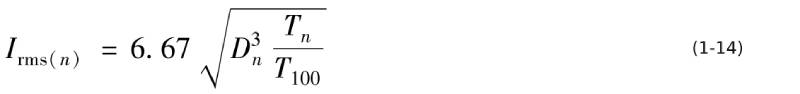
In order to make the analysis simple and representative, the total current effective value of the support capacitor, the 100Hz current effective value and the switching frequency component current effective value of the six input voltages of 85V, 110V, 130V, 176V, 220V, and 264V can be analyzed to understand the different The current that the support capacitor can withstand under input voltage conditions.
When the input voltage is different and the output voltage is 400V, the average output DC value is 2.5mA/W. The 100Hz ripple current is 1 √2 of the DC current component, which is 1.77mA/W.
Under the condition of 85V input voltage, the effective value of the input current is 11.76mA/W, the peak value of the input current is 16.64mA/W, and the effective value of the current flowing through the output diode is 5.94mA/W. The total effective ripple current flowing through the support capacitor is 5.38mA/W, of which the 100Hz ripple current component is 1.77mA/W and the switching frequency ripple current component is 5.09mA/W. The total effective ripple current value is 3.04 times the effective value of the 100Hz ripple current. The effective value of the switching frequency ripple current is 2.88 times the effective value of the 100Hz ripple current.
Under the condition of 110V AC input voltage, the effective value of the input current is 9.09mA/W, the peak value of the input current is 12.86mA/W, and the effective value of the output current is 5.22mA/W. The total effective ripple current flowing through the support capacitor is 4.59mA/W, of which the 100Hz ripple current component is 1.77mA/W and the switching frequency ripple current component is 4.23mA/W. The total effective ripple current value is 2.59 times the effective value of the 100Hz ripple current. The effective value of the switching frequency ripple current is 2.39 times the effective value of the 100Hz ripple current.
Under the condition of 130V AC input voltage, the effective value of the input current is 7.69mA/W, the peak value of the input current is 10.88mA/W, and the effective value of the output current is 4.81mA/W. The total effective ripple current flowing through the support capacitor is 4.1mA/W, of which the 100Hz ripple current component is 1.77mA/W and the switching frequency ripple current component is 3.7mA/W. The total ripple current effective value is 2.31 times the 100Hz ripple effective value. The effective value of the switching frequency ripple current is 2.09 times the effective value of the 100Hz ripple current.
6.3 Analysis of output current status under 176~264V conditions
When powered at 220V voltage level, the AC input voltage range is limited to 176~264V
The output current DC average value is 2.5mA/W.
Under the condition of 176V input voltage, the effective value of the input current is 5.68mA/W, the peak value of the input current is 8.04mA/W, and the effective value of the output current is 4.13mA/W. The total effective ripple current flowing through the support capacitor is 3.29mA/W, of which the 100Hz ripple current component is 1.77mA/W and the switching frequency ripple current component is 2.77mA/W. The total ripple current effective value is 1.86 times the 100Hz ripple effective value. The effective value of the switching frequency ripple current is 1.56 times the effective value of the 100Hz ripple current.
Under the condition of 220V AC input voltage, the effective value of the input current is 4.55mA/W, the peak value of the input current is 6.43mA/W, and the effective value of the output current is 3.67mA/W. The total ripple current flowing through the support capacitor is 2.68mA/W, of which the 100Hz ripple current component is 1.77mA/W and the switching frequency ripple current component is 2.02mA/W. The total ripple current effective value is 1.51 times the 100Hz ripple effective value. The effective value of the switching frequency ripple current is 1.14 times the effective value of the 100Hz ripple current.
Under the condition of 264V AC input voltage, the effective value of the input current is 3.79mA/W, the peak value of the input current is 5.36mA/W, and the effective value of the output current is 3.37mA/W. The total ripple current flowing through the support capacitor is 2.26mA/W, of which the 100Hz ripple current component is 1.77mA/W and the switching frequency ripple current component is 1.4mA/W. The total effective ripple current value is 1.27 times the effective value of the 100Hz ripple. The effective value of the switching frequency ripple current is 79% of the effective value of the 100Hz ripple current.
6.4 Conclusion and analysis
Within the AC input voltage range of 85 to 264V, the ripple current components per unit output power corresponding to each key input voltage value are shown in Table 1-2 and Table 1-3.
Table 1-2 Ripple current flowing through the support capacitor at critical input voltages
Table 1-3 The relationship between the ripple current flowing through the support capacitor and the 100Hz harmonic current under key input voltages
It can be seen from Table 1-2 and Table 1-3 that under the same working conditions, the ripple current of the capacitor in the rectifier circuit with active power factor correction function is significantly lower than that without active power factor correction function. The value of the rectifier circuit is about 1/4 (85V) or 1/3 (220V) of the rectifier circuit without active power factor correction. This can significantly improve the life of electrolytic capacitors. Among them, the 100Hz ripple current component is less than 10% (85V) or 30% (220V) of the non-active power factor correction rectifier circuit.
For medium-power switching power supplies such as 500W switching power supplies, based on a 3% change in output voltage, the minimum capacitance can be selected from 150 to 180 μF. In this capacitance range, an electrolytic capacitor with a withstand voltage of 450V can withstand an effective ripple current of 0.95A ( 85℃) or 0.82A (105℃). The maximum ripple current corresponding to 500W output power is 2690mA (input voltage is 85V) or 1645mA (input voltage is 176V). Obviously, according to the minimum capacitance selection, the ripple current capability of the electrolytic capacitor will not meet the requirements. The capacitance needs to be selected according to the ripple current requirement. Select the capacitance according to 1μF/W. For example, the corresponding ripple current tolerance of 470μF is 1.5A (105℃) or 2.2A (85℃) to meet the requirements.
If you must choose according to 3W/μF, the life of the electrolytic capacitor will be significantly shortened, and it will not follow the rule that the life of the electrolytic capacitor doubles for every 10°C decrease in temperature.
Analysis of the working state of capacitors—Analysis of the ripple current of the support capacitor in the current continuous mode using the international common voltage of 85~264V
7.Analysis of the working state of capacitors—Analysis of the ripple current of the support capacitor in critical current mode
7.1 Analysis of support capacitor current in current critical mode
The power factor correction circuit has extremely high requirements on the reverse recovery characteristics of the output diode, and usually ultra-fast reverse recovery diodes with a voltage rating of 600V cannot meet the requirements. In the mid-1990s, in order to meet the performance requirements of power factor correction circuits, two ultra-fast reverse recovery diodes with a withstand voltage of 300V were even used in series. In the 2010s, the price of silicon carbide Schottky diodes began to drop significantly, and high-power power factor correction circuits began to use silicon carbide Schottky diodes with almost no reverse recovery characteristics.
In order to reduce the cost as much as possible, the power factor correction circuit in the cheap low-power switching power supply has to use ultra-fast reverse recovery diodes with general performance or even fast reverse recovery diodes. In order to avoid the reverse recovery problem of the diode, the current critical operating mode is selected to reduce the impact of the diode reverse recovery. The resulting change in circuit performance is that the diode output current amplitude is twice that of the current continuous mode, and the current flowing through the support capacitor The effective value of the ripple current will also change.
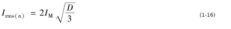
In addition to the current continuous mode, the power factor correction circuit also has a current critical mode. In this working mode, the input/output voltage relationship of the power factor correction circuit is still equation (1-3), except that the current waveform changes from a rectangular wave to a sawtooth wave, and the duty cycle relationship remains unchanged. Relative to each switching cycle, the relationship between the effective value of each current pulse, the peak value, and the duty cycle is:
Compared with the rectangular wave current in the current continuous mode, under the same input and output conditions, the current amplitude in the current critical operating mode is twice that of the current continuous mode, which is
 The effective value of the rectangular wave current is

Compared with the two, the effective value of the sawtooth wave current is √4/3 times that of the rectangular wave.
It should be noted that this current is used to increase the diode output current of the power factor correction circuit. It has a DC component. Its DC component is used as the circuit output, and the AC component flows into the support capacitor, so its DC component needs to be deducted.
7.2 Analysis of output current status under 85~130V conditions
Regardless of whether it is current continuous mode, critical mode or discontinuous mode, the average output DC current of a power factor correction circuit with an output voltage of 400V is 2.5mA/W, and the 100Hz ripple current flowing into the support capacitor is also 1.77mA/ W.
Under the condition of 85V input voltage, the total effective ripple current flowing through the support capacitor is 6.38mA/W, of which the 100Hz ripple current component is 1.77mA/W and the switching frequency ripple current component is 6.13mA/W. The total effective ripple current value is 3.6 times the effective value of the 100Hz ripple current. The effective value of the switching frequency ripple current is 3.46 times the effective value of the 100Hz ripple current.
Under the condition of 110V AC input voltage, the effective value of the total ripple current flowing through the support capacitor is 5.48mA/W, of which the 100Hz ripple current component is 1.77mA/W and the switching frequency ripple current component is 5.19mA/W. The total effective ripple current value is 3.09 times the effective value of the 100Hz ripple current. The effective value of the switching frequency ripple current is 2.93 times the effective value of the 100Hz ripple current.
Under the condition of 130V AC input voltage, the total effective ripple current flowing through the support capacitor is 4.95mA/W, of which the 100Hz ripple current component is 1.77mA/W and the switching frequency ripple current component is 4.63mA/W. The total effective ripple current value is 2.79 times the effective value of the 100Hz ripple current. The effective value of the switching frequency ripple current is 2.62 times the effective value of the 100Hz ripple current.
7.3 Analysis of output current status under 176~264V conditions
When powering at 220V voltage level, the AC input voltage range is limited to 176~264V, and the average output DC current is 2.5mA/W.
Under the condition of 176V input voltage, the total effective ripple current flowing through the support capacitor is 4.06mA/W, of which the 100Hz ripple current component is 1.77mA/W and the switching frequency ripple current component is 3.65mA/W. The total effective ripple current value is 2.29 times the effective value of the 100Hz ripple current. The effective value of the switching frequency ripple current is 2.06 times the effective value of the 100Hz ripple current.
Under the condition of 220V AC input voltage, the total effective ripple current flowing through the support capacitor is 3.41mA/W, of which the 100Hz ripple current component is 1.77mA/W and the switching frequency ripple current component is 2.92mA/W. The total effective ripple current value is 1.93 times the effective value of the 100Hz ripple current. The effective value of the switching frequency ripple current is 1.65 times the effective value of the 100Hz ripple current.
Under the condition of 264V AC input voltage, the total effective ripple current flowing through the support capacitor is 2.98mA/W, of which the 100Hz ripple current component is 1.77mA/W and the switching frequency ripple current component is 2.4mA/W. The total effective ripple current value is 1.68 times the effective value of the 100Hz ripple current. The effective value of the switching frequency ripple current is 1.36 times the effective value of the 100Hz ripple current.
7.4 Conclusion and analysis
Within the AC input voltage range of 85 to 264V, the ripple current components per unit output power corresponding to each key input voltage value are shown in Table 1-4 and Table 1-5.
Table 1-4 Ripple current flowing through the support capacitor at critical input voltages
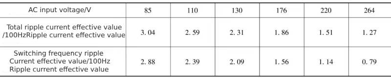
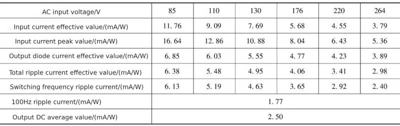 Table 1-5 The relationship between the ripple current flowing through the support capacitor and the 100Hz harmonic current under key input voltages
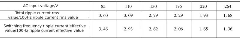
It can be seen from Table 1-4 and Table 1-5 that under the same working conditions, the ripple current of the capacitor of the rectifier circuit with active power factor correction function is significantly lower than that without active power factor correction function. The value of the rectifier circuit is about 1/3 of the rectifier circuit without active power factor correction in the full voltage range state.
Selection of capacitance: For example, in a 200W switching power supply, the power factor correction unit works in current critical mode. When the input voltage is 85V, the ripple current flowing through the supporting capacitor is 1276mA. If a 120μF/450V electrolytic capacitor is selected, is the ripple current tolerance sufficient? ? For example, the CD110Z (85℃/5000h) series electrolytic capacitor has a ripple current withstand capacity of 655mA. Obviously, under full power operation, the lifespan cannot be guaranteed when using 120μF/450V electrolytic capacitors. If the power supply only works at the 220V voltage level, the ripple current flowing through the support capacitor is 658mA, which only meets the ripple requirements of the power factor correction circuit unit.
Analysis of the working status of capacitors—The above is the analysis of the ripple current of the support capacitor in the current critical mode.
8.Analysis of the working state of capacitors—Summary of this chapter
The power factor correction circuit is a rectifier circuit whose fundamental purpose is to eliminate the high-order harmonic current generated by the rectifier from entering the AC power grid.
The output filter capacitor of the power factor correction circuit is connected to its output end and needs to absorb all the AC current components of its output to support the stability of the DC output voltage. Therefore, the output filter capacitor can be called a support capacitor.
Under unit output power conditions, the average value of DC output current and the effective value of 100Hz ripple current have a fixed relationship with the output voltage and do not change with the AC input voltage. The 100Hz ripple current of the non-power factor corrected rectifier and filter circuit increases with the decrease of the input voltage, which is inversely proportional to the relationship.
In order to easily compare the support capacitor ripple current state in the current continuous mode with the current critical mode, the data in Table 1-2 and the data in Table 1-4 can be listed in one table, see Table 1-6, and Table 1-3 Listed in the same table as the data in Table 1-5, see Table 1-7.
Table 1-6 Comparison of ripple current data flowing through the support capacitor in current continuous mode and current critical mode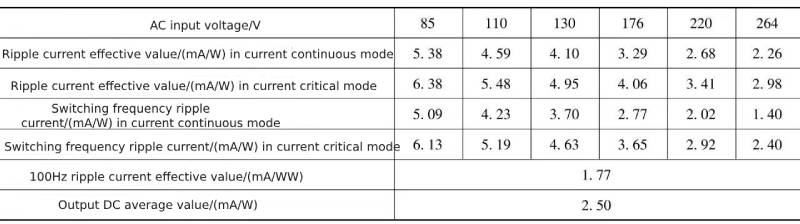 Table 1-7 Comparison of ripple current and 100Hz harmonic current flowing through the support capacitor in current continuous mode and current critical mode
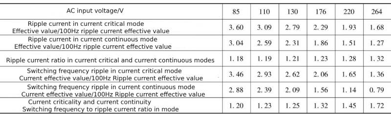
Compared with the rectifier filter circuit without power factor correction function, under the same output power state, the ripple current flowing through the support capacitor is significantly reduced, which is beneficial to reducing the capacitance of the electrolytic capacitor when selecting the support capacitor.
The rectifier filter circuit without power factor correction function only has a ripple current of twice the power frequency and a small amount of multi-frequency ripple current, and does not produce high-frequency ripple current. Therefore, only the parameters of 120Hz electrolytic capacitors are considered in the traditional concept of electrolytic capacitor parameters.
In the output capacitor (support capacitor) of the power factor correction circuit, the ripple current flowing through the 100Hz frequency is significantly reduced, and the low-frequency impedance requirements dominated by the aluminum oxide film are relatively reduced. At the same time, the switching frequency ripple current is generated, and in most operating conditions significantly exceeds the 100Hz ripple current, becoming the main component of the ripple current flowing through the support capacitor.
It can be seen from Table 1-6 and Table 1-7 that the ripple current flowing into the support capacitor in the power factor correction circuit in current critical mode is higher than that in the power factor correction circuit in current continuous mode.
Based on the above analysis, the power factor correction circuit can significantly reduce the ripple current of the output capacitor, that is, the 100Hz ripple current value.
After power factor correction is introduced, the ripple current component flowing through the output capacitor has a current component at the switching frequency, and this current component is greater than the 100Hz ripple current component in most cases. Therefore, the output capacitor in a circuit with power factor correction must consider the high frequency performance of the capacitor. Since the switching frequency of most power factor correction circuits is 50kHz or above, it is necessary to evaluate the high-frequency ripple current performance of electrolytic capacitors, especially high-frequency ripple current tolerance and high-temperature load life experiments with high-frequency ripple current.
Not only lead-pin electrolytic capacitors must be used in power factor correction circuits, but pin-type electrolytic capacitors must also be used in power factor correction circuits. Therefore, not only lead-pin electrolytic capacitors require 100kHz ripple current parameters and ESR parameters, but pin-type electrolytic capacitors also need Provides 100kHz ripple current parameters and ESR parameters.
Through research, most domestic lead-pin electrolytic capacitors have not undergone high-temperature load life tests for high-frequency ripple current. The given 100kHz ripple current parameter is calculated from the 120Hz ripple current through the ESR equivalent heating of 100kHz and 120Hz. owned.
Due to the parasitic inductance of the electrolytic capacitor, the maximum current density is at the aluminum foil at the guide pin or conductor strip. For the positive electrode, excessive current density, especially at high temperatures, may cause hydration effects. The result of the hydration effect is that the ESR there becomes larger. That is to say, once the hydration effect there is more obvious, the ripple current will no longer flow through the aluminum foil there, and the ripple current will be transferred to the adjacent aluminum foil.
Therefore, due to the excessive local current density at high temperature, the aluminum foil near the guide pin will first enter the hydration reaction and gradually expand, eventually causing the capacitance of the electrolytic capacitor to drop to the lower limit of the initial capacitance and the ESR to rise to the initial value. upper limit, at which point the electrolytic capacitor fails in performance. However, in practical applications, this failure is not visible in the appearance of the circuit until the electrolytic capacitor has a convex bottom or even a bursting phenomenon. This phenomenon cannot be found in the 120Hz high-temperature load life test because the effect of 120Hz on the parasitic inductance of the electrolytic capacitor is minimal.
Since electrolytic capacitors inevitably flow through high-frequency ripple current, current electrolytic capacitors require a high-temperature load life test of 100kHz high-frequency ripple current to determine the authenticity of the electrolytic capacitor’s 100kHz lifespan.
Due to the existence of parasitic inductance in the core of electrolytic capacitors, especially large-diameter lead-pin electrolytic capacitors, it is not recommended to apply the frequency conversion factor of ripple current when selecting a capacitor that has not passed the high-temperature load life test of 100kHz high-frequency ripple current.
Analysis of the working state of capacitors—The above is the summary of this chapter
Summarize:
Analysis of the working state of capacitors—It mainly talks about the problem of power factor correction, the working status of the most commonly used boost power factor correction circuit, the minimum capacitance, the ripple current of the supporting capacitor in the current continuous mode, and the supporting capacitor in the current continuous mode when using the international common voltage of 85 ~ 264V. Ripple current, support capacitor ripple current analysis in critical current mode, etc.For more details please click:https://solidcapacitor.com

