1 Operation and maintenance management of capacitor filter devices
1.1 Precautions for operation and maintenance of filters and parallel capacitor devices
1.1.1 Monitoring of capacitor unbalanced current operation
The most important function of AC filters and parallel capacitors is to provide reactive power for DC systems. When reactive power does not meet the absolute minimum filter (absolute minimum filter capacity limit, the absolute minimum number of filter groups required to prevent overload of filter equipment. In any case, this condition must be met), it may lead to power reduction accidents in the DC system. During the operation of the DC system, operators should pay attention to the control mode of reactive power, capacitor filter devices, the number of AC filters and parallel capacitors, the switching of DC system speed filters when power changes, and the standby status of filters and parallel capacitors. The above are matters that need attention from the perspective of the safe and stable operation of the entire DC system by AC wave generators and parallel capacitor devices.
As for the AC and DC filters and shunt capacitors themselves, operators should strengthen the monitoring of the unbalanced current of the bridge arm during the operation of the equipment. Although the AC and DC filters and shunt capacitors are divided into several unbalanced current alarm values, the corresponding alarm will appear in the background when the set value is reached, but regular attention to the unbalanced current situation and trend analysis can indirectly grasp the operation of the capacitor in advance, and focus on the filter group with abnormal unbalanced current in daily operation and maintenance.
The following example uses a group of filters in Yinchuan East Converter Station in the Ningdong to Shandong DC project as an example to explain how the operation and maintenance personnel conduct unbalanced current trend analysis: regularly record the unbalanced current of the three phases of the capacitor (note: generally, regular means a certain time interval, but the analysis here mainly refers to the horizontal data comparison between the three phases. It does not particularly emphasize that the period of recording data must be certain, but the recording time of the three phases must be consistent to ensure that the three phases are under the same operating conditions and environmental conditions. The purpose is to increase the comparability of the data, because for the capacitor tower that has been accurately balanced before commissioning, the influence of the outside world and the system on the unbalanced current may be the main factor). By analyzing the trend of unbalanced current changes, a qualitative analysis can be performed on a certain phase of the capacitor. As shown in Figure 1, the unbalanced current of the 3624HP11/13 filter recorded over a period of time is used to draw the following trend analysis chart using the Excel table function. The trend analysis chart shows that before February 28, 2012, the unbalanced current change trends of the three phases of the filter group were basically the same (data recorded under the same operating conditions and environment). After March 6, the change trends of the unbalanced currents of phases B and C were still the same, while the unbalanced current trend chart of phase A had left the “team”. The unbalanced current of phase A suddenly decreased significantly, indicating that the capacitance value of the capacitor bridge arm of phase A changed significantly, making the bridge arm more balanced. Conversely, the change in capacitance value may also make the bridge wall more unbalanced. In both cases, the operation and maintenance personnel should focus on strengthening monitoring.
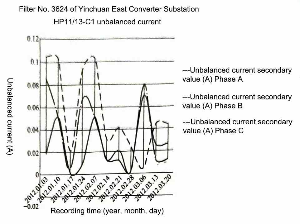
Figure 1 Analysis of the trend of unbalanced current changes
When the filter, capacitor filter devices and parallel capacitor are newly put into operation or manually switched on and off, the following should be noted:
(1) When the new equipment is put into operation for the first time, it should be closed and impacted 3 times at the rated voltage. The time interval between each closing and opening should be at least 10 minutes to ensure that the residual voltage of the capacitor is discharged to the required range.
(2) After the new operation (including live debugging) for about 2 hours, infrared temperature measurement should be performed on capacitor filter devices and other equipment.
(3) When a new capacitor is put into operation for the first time (or after replacing a faulty capacitor), the unbalanced current needs to be initialized and calibrated in the protection device.
(4) For newly put into operation filters and shunt capacitors, the recording data of the equipment when it is put into operation should be printed on the recording device, especially for filters and shunt capacitors with phase selection and closing devices, so as to analyze whether the recording data is normal, and then check whether the phase selection and closing device after debugging is operating normally.
1.1.2 Monitoring of leakage current and action status of lightning arresters in the filter field
The main purpose of monitoring the leakage current and action status of lightning arresters is to check whether the configuration and parameter settings of the lightning arrester of the overvoltage protection device in the filter meet the design requirements and whether they can meet the purpose of protecting the operating equipment. Usually, the number of lightning arrester actions and leakage current in the filter fence are recorded regularly, and the operation status of the lightning arrester is analyzed in combination with the number of filter switching times, which can be used to understand the operation status of the lightning arrester from the side.
1.1.3 Monitoring of the operation of capacitors in filters
The operation monitoring mainly refers to whether the capacitor joints are hot during operation, whether a single capacitor is bulging or leaking oil, whether there are foreign objects in the capacitor tower, etc. These are the main causes of capacitor failure and should be monitored more closely.
The above three items are the key points that operation and maintenance personnel need to pay attention to during the operation and maintenance of filters, capacitor filter devices and parallel capacitor equipment. In essence, these contents are still the core of daily operation and maintenance of converter station filter equipment. Specific and detailed operation and maintenance items will be explained in detail in the form of tables in Section 3.
1.2 Basic requirements for operation and maintenance of filter and parallel capacitor equipment
For the role of filters and parallel capacitors in DC systems, the following operation regulations should be paid attention to:
(1) Under normal operation of the DC system, the reactive power control mode of the capacitor filter devices and parallel capacitor should be selected as automatic.
(2) Under normal operation of the DC system, when replacing the filter group, the reactive power control should be switched to manual mode.
(3) When manually replacing filters and parallel capacitors, the selection of first-in and then-out should be followed.
(4) When the filter and parallel capacitor are out of service, first open the circuit breaker, then open the load-side disconnector, and finally open the busbar-side disconnector. When the filter and parallel capacitor are put into service, the operation sequence is the opposite.
(5) If a small amount of oil leakage is found in the capacitor during operation, and the capacitor is not abnormally heated by infrared temperature measurement, it is allowed to continue to operate. The monitoring of various state quantities of the capacitor (unbalanced current, infrared temperature measurement, appearance, etc.) should be strengthened.
(6) Under normal circumstances, infrared temperature measurement of the equipment should be carried out once a month, and infrared temperature measurement should be carried out every week during the peak summer period.
(7) If abnormal discharge sound is found in the equipment during inspection, ultraviolet discharge detection of the equipment should be carried out as soon as possible.
(8) Regularly record the number of lightning arrester actions and leakage current in the filter field.
(9) Regularly record the unbalanced current of the filter and parallel capacitor equipment and analyze it.
(10) Conduct a night inspection of the equipment once a week to check whether there is any visible abnormal discharge in various filter equipment.
2 Daily maintenance of capacitor filter devices
Due to the particularity of DC transmission systems, the non-stop maintenance items and cycles of AC and DC filters, capacitor filter devices and shunt capacitors are also different from those of ordinary AC capacitor groups. The main items of the former are as follows.
(1) Daily periodic routine inspections. For details, see Table 1.
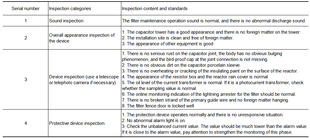
Table 1 Inspection contents and standard table of filters and shunt capacitors
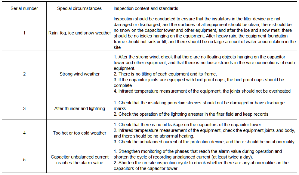
(2) When the environment and operating conditions are relatively bad, it is necessary to conduct characteristic inspections on filters and shunt capacitor devices. For details, see Table 2:
Table 2 Inspection contents and standard table of special working conditions
3 Emergency treatment during device operation
In DC transmission systems, AC filters and shunt capacitors provide reactive power and filter harmonics for DC systems, and DC filters are used to filter harmonics on the DC side to prevent interference with communications. Usually, there is sufficient spare capacity for filters and shunt capacitors in DC converter stations. Therefore, when a group fails, the system will automatically put other spare reactive power reserves into use. However, since capacitors are relatively easy to damage during operation, operation and maintenance personnel need to take correct handling methods in some emergency disposal to avoid power loss or even lockout of the DC system due to filter problems. The following introduces some common abnormal situations in filter operation.
3.1 The absolute minimum number of filter groups does not meet the requirements during operation
3.1.1 Phenomenon description
The monitoring system background reports that the absolute minimum filter is not met, and an emergency fault alarm is issued.
3.1.2 Operation personnel processing steps
(1) First, report the situation to the on-duty dispatcher of the National Power Dispatching and Communication Center (hereinafter referred to as the National Dispatching Center) and the head of the station, and closely monitor the operation status of the DC system.
(2) The duty officer checks whether the reactive power control mode is normal.
(3) Check whether the capacitor filter devices, filter switch control mode and energy storage are normal.
(4) If all of the above are normal, apply to the National Dispatching Center for spare AC filters or parallel capacitors when necessary.
(5) If there is no available spare filter (parallel capacitor) for the time being, the on-site filter maintenance progress should be accelerated to restore the filter standby as soon as possible.
3.2 Oil leakage of filter capacitor
3.2.1 Description of phenomenon
Inspection found that the filter capacitor was leaking oil.
3.2.2 Processing steps
(1) Observe the oil leakage rate of the capacitor. If the oil leakage is very weak, the operator should strengthen the oil leakage monitoring. At the same time, the unbalanced current of the capacitor should be monitored regularly. If it is at a low level, it can continue to operate (generally, capacitors with slight oil leakage can continue to operate), but maintenance should be arranged as soon as possible.
(2) If the leakage rate is very fast and a large oil stain has formed on the ground, the national dispatching department should be requested to shut down the faulty filter for maintenance.
(3) Take safety measures for the filter that has been out of operation and notify the maintenance personnel to handle it immediately.
3.3 Overheating of the AC filter/shunt capacitor equipment connector
3.3.1 Description of phenomenon
Infrared temperature measurement shows that the temperature of the capacitor filter devices, filter or shunt capacitor equipment connector is too high.
3.3.2 Processing steps
(1) Report to the head of the converter station, closely monitor the operation of the entire equipment, shorten the infrared temperature measurement cycle of the connector, and monitor whether the heating has a trend of further deterioration.
(2) According to the requirements of DL/T 664-2008 “Application Specification of Infrared Diagnosis Technology for Live Equipment”, determine the level of heating defects. If it is an emergency defect, apply to the national dispatching department to withdraw the filter group (consider the operation needs of the DC system and follow the principle of first-in, then-out), and carry out emergency repairs.
3.4 AC filter group protection action
3.4.1 Phenomenon description
(1) The AC filter protection action alarm of the monitoring system background.
(2) The large filter switch trips and is locked.
3.4.2 Processing steps
(1) Whenever the large filter of the converter station trips, report it to the national dispatching department and the superior supervisor immediately.
(2) At the same time, check the input status of the standby AC filter (parallel capacitor).
(3) Check whether the DC system has power reduction.
(4) Check the operation status of the equipment in the fault area. If the small filter switch does not trip, pull it open manually immediately.
(5) Check the DC system power and AC bus voltage, and apply to the national dispatching department to adjust the DC system operating power if necessary.
(6) On-site inspection of capacitor filter devices, filters or parallel capacitor equipment within the protection action range. If obvious faults such as flashover and fracture are found, apply to the National Dispatching Office to transfer the corresponding equipment to maintenance status according to the fault location, take safety measures, and notify the maintenance personnel to handle it.
(7) If no obvious primary equipment fault is found during the on-site inspection, notify the maintenance personnel to check and analyze the secondary circuit and the cause of the protection action.
(8) If the failure of the small group filter does not trip, causing the failure to start the large group filter to trip, the small group filter should be withdrawn and transferred to maintenance, and other small group filters in the large group should be put back into operation. If the large group filter is indeed tripped due to protection action, the equipment should be repaired immediately.
3.5 AC filter C1 capacitor unbalance protection alarm
3.5.1 Phenomenon description
(1) The monitoring system background AC filter C1 capacitor unbalance protection stage I alarm.
(2) The monitoring system background AC filter C1 capacitor unbalance protection stage II alarm, the filter circuit breaker trips with a delay of 2h.
(3) The unbalanced protection stage III of the capacitor C1 of the monitoring system background AC filter is activated, and the circuit breaker trips.
3.5.2 Processing steps
(1) Immediately report to the on-duty dispatcher of the National Dispatch Center and notify the supervisor of this station.
(2) When a stage I alarm occurs, if system conditions permit, the faulty AC filter can be shut down for processing. If it is not shut down, monitoring should be strengthened. If the alarm signal disappears by itself, it should be reported to the national dispatcher in a timely manner.
(3) When a stage II alarm occurs, if the spare AC filter or capacitor filter devices is in operating conditions, the faulty AC filter should be shut down for processing within 2 hours; if there is no spare AC filter that can be operated, the faulty AC filter should be shut down by reducing the DC transmission power.
(4) When a stage III trip occurs, check whether the spare filter is in normal operation, report to the dispatcher and strengthen monitoring.
(5) Check on-site for obvious faults in the filter capacitor.
(6) Take safety measures for the shut-down filter and notify the maintenance personnel to handle it.
3.6 AC filter differential protection action
3.6.1 Phenomenon description
Monitoring system alarm, event record, fault recording action; filter circuit breaker tripping; filter circuit breaker locking.
3.6.2 Processing steps
(1) The operator immediately reports to the on-duty dispatcher of the national dispatch and the supervisor of this station.
(2) Check that the standby filter is operating normally, report to the dispatcher and strengthen monitoring.
(3) Check on-site for obvious faults in the equipment within the filter protection range.
(4) Take safety measures for the withdrawn filter and notify the maintenance personnel to immediately handle the fault.
3.7 Alarm signals of AC filter resistor overload protection and reactance overload protection
3.7.1 Phenomenon description
(1) Monitoring system overload stage I alarm.
(2) Monitoring system overload stage II alarm, filter circuit breaker trips with a delay of 40 minutes;
(3) Monitoring system overload stage III emergency fault, filter circuit breaker trips.
3.7.2 Processing steps
(1) The operator should immediately report the on-site situation to the on-duty dispatcher and the superior supervisor of the National Dispatching Office.
(2) When the overload stage I alarm occurs, if the system conditions permit, the faulty AC filter or capacitor filter devices can be withdrawn from operation for processing. If the conditions for withdrawal are not met for the time being, monitoring should be strengthened. If the alarm signal disappears by itself, it should be reported to the National Dispatching Office in a timely manner.
(3) When an overload II alarm occurs, if the standby AC filter is in operating condition, the faulty AC filter should be shut down within 40 minutes for inspection and processing; if there is no standby AC filter available, the faulty AC filter should be shut down within 40 minutes by reducing the DC transmission power.
(4) When an emergency overload fault occurs, the on-site inspection of all filters should be carried out to ensure that they are operating normally, report to the dispatcher and strengthen monitoring.
(5) On-site inspection of the overloaded AC filter for obvious faults.
(6) Take safety measures for the shut-down AC filter and notify the maintenance personnel to handle the fault.
3.8 Reactive load shedding action
3.8.1 Phenomenon description
(1) The monitoring system background reports an emergency fault alarm of reactive power dissatisfaction and power reduction, which may be related to the working status of the capacitor filter devices.
(2) DC power reduction.
3.8.2 Processing steps
(1) Immediately report the situation to the on-duty dispatcher of the National Dispatching Office and the supervisor of this station.
(2) If a reactive load shedding alarm occurs during the power increase process, the reactive power control mode and the on-site filter control mode should be checked immediately to see if they are normal. After manually or automatically switching on the standby AC filter, apply to the National Dispatch Center to restore the original power operation.
(3) If the reactive load shedding action occurs due to filter tripping, the reactive power control mode and the on-site standby filter control mode should be checked immediately to see if they are normal. After manually or automatically switching on the standby AC filter, apply to the National Dispatch Center to restore the original power operation.
(4) If there is no standby AC filter or the standby filter is available on site, apply to the National Dispatch Center to adjust the system power.
(5) Notify the maintenance personnel to conduct inspection and processing.
3.9 DC filter overload protection action
3.9.1 Phenomenon description
(1) Monitoring system background alarm, event recording, and fault recording action.
(2) Remove the DC filter.
(3) When the number of DC filter groups does not meet the system requirements or a large fault current (greater than 180A, this value varies slightly depending on the project) occurs, the converter is locked.
3.9.2 Processing steps
(1) The operator shall immediately report the situation to the on-duty dispatcher of the National Dispatch Center and strengthen monitoring.
(2) Take safety measures for the filter that has been withdrawn and notify the maintenance personnel to handle it.
3.10 DC filter C1 capacitor unbalance protection alarm
3.10.1 Phenomenon description
(1) The monitoring system background DC filter C1 capacitor unbalance protection stage I alarm may be related to the working status of the capacitor filter devices.
(2) The monitoring system background DC filter C1 capacitor unbalance protection stage II alarm and delay 2h to cut off the DC filter.
(3) The monitoring system background DC filter C1 capacitor unbalance protection stage III alarm and cut off the DC filter. When the number of DC filter groups does not meet the system requirements, the converter is locked.
3.10.2 Processing steps
(1) The operator on duty shall report the situation to the on-duty dispatcher of the National Dispatch Center and the supervisor of this station.
(2) When the background stage I alarm occurs, if the DC system conditions permit, the faulty DC filter can be withdrawn from operation for processing.
(3) When the backstage II alarm occurs, the faulty DC filter should be shut down within 2 hours for processing.
(4) When the backstage III fault trips, the DC system operation should be monitored more closely and the operation of the DC filter in the station should be reported to the dispatcher.
(5) Check whether the capacitor filter devices group, reactor, resistor or other primary equipment of the faulty DC filter have obvious abnormalities.
(6) Take safety measures for the shut-down filter and notify the maintenance personnel to handle it.
3.11 DC filter differential protection action
3.11.1 Phenomenon description
(1) Monitoring system backstage alarm, event recording, and fault recording start.
(2) Cut off the DC filter.

