1 Definition of aluminum electrolytic capacitors
The physical concept of aluminum electrolytic capacitors is a discrete component consisting of two conductive plates with a material with dielectric characteristics placed in the middle. The material with dielectric characteristics here is called insulating material in electrical engineering, dielectric in physics, and dielectric in the aluminum electrolytic capacitors industry.
Suppose the structure of a flat plate capacitor is as shown in Figure 1: the capacitance of the capacitor is C, the plate area is S, the dielectric permittivity is ε, and the dielectric thickness is d, and the two plates are charged with +Q and -Q respectively, then the charge per unit area σ=Q/S. According to the basic formula of physical electrostatics, the dielectric electric field strength between the two plates is:
![]() (1)
(1)
In the formula, ε0—vacuum permittivity;
εr—relative permittivity.
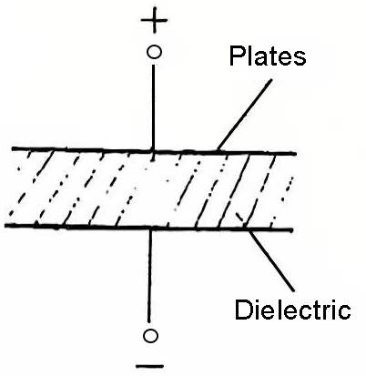
Figure 1 Schematic diagram of the structure of a flat plate capacitor
And the product of the relative permittivity εr and the vacuum permittivity ε0 is called the permittivity ε, that is, ε=ε0εr. Because U=Ed, C=Q/U, then:
![]()
Where U is the applied voltage, in V. If S is in cm2′, d is in cm, and ε0 is for vacuum:
In electrostatic units ε0=1
In practical units
![]()
Substituting into the above formula, we get the capacitance relationship of the plate capacitor commonly used in engineering:
![]() (2)
(2)
or
![]()
Where: S is the effective surface area of the electrode plate, cm2;
d is the dielectric thickness, that is, the distance between the two plates, cm.
The unit of capacitance is farad (F) in the practical unit system. When using farad, it is too large and inconvenient to use. Microfarad (μF) or picofarad (pF) are often used. The relationship between them is: 1F-106μF=1012pF.
Regarding the concept of the physical term permittivity, it is necessary to introduce it here:
permittivity is a physical term announced by the National Natural Science Terminology Review Committee in 1996. In engineering technology, relative permittivity is usually used to describe the dielectric properties of dielectrics. At present, in some books and materials, the word “relative” is often not added but “permittivity”. In fact, the “capacitance” here is not the same as the “permittivity”. “Rate” refers to relative permittivity. Except for the relative permittivity of air, which is approximately equal to , the relative permittivity of other dielectrics is greater than 1. In the International System of Units, relative permittivity is dimensionless, while vacuum permittivity is dimensioned (F/m). Furthermore, in the past, ε, ε0 and εr were customarily referred to as dielectric constant, vacuum dielectric constant and relative dielectric constant, respectively, which are not recommended names.
In addition, from the perspective of physical electrostatics, capacitors, as the name implies, have the function of storing energy. The energy they store is W:
![]()
Example: A flat plate capacitor, the electrode surface area is 2cm2, the dielectric thickness is 0.2mm, and the relative permittivity is 8.4. Find the capacitance of the capacitor.
Solution: Calculate according to formula (1):
![]()
Among capacitors, there is a type of capacitor with a special structure called electrolytic capacitor. The so-called electrolytic capacitor is a capacitor with two plates, one positive electrode and one negative electrode. The anode is made of a specific valve metal, and an extremely thin oxide film with unidirectional conductivity is generated on the metal surface by electrochemical methods as a medium, while the cathode is usually a liquid or solid electrolyte that can generate and repair the dielectric oxide film. This is a capacitor with a special structure and special process. The specific valve metal here refers to metals such as aluminum, tantalum, niobium and titanium, because the metal oxides generated by them, Al2O3:, Ta2O5, Nb2O5, and TiO2, all have unidirectional conductivity.
There are many types of electrolytic capacitors, so their classification can be carried out from different angles:
(1) Classification by valve metal type: aluminum electrolytic capacitors, tantalum electrolytic capacitors and tantalum-niobium alloy electrolytic capacitors, etc.
(2) Classification by electrolyte state: there are liquid (wet) electrolytic capacitors and solid electrolytic capacitors.
(3) Classification by the state of the anode: there are foil-wound electrolytic capacitors and sintered electrolytic capacitors.
Of course, they can also be classified by purpose, working environment, and performance. This book mainly describes the most commonly used general-purpose foil-shaped wet aluminum electrolytic capacitor.
2 Structural characteristics of aluminum electrolytic capacitors
The basic structure of general-purpose aluminum electrolytic capacitor is a foil-wound structure, as shown in Figure 2. The anode is an aluminum metal foil dielectric, which is a valve metal oxide film Al2O3 formed on the surface of the anode metal foil by electrochemical methods. The cathode is a working electrolyte adsorbed by porous electrolytic paper, which makes the aluminum electrolytic capacitors unique in structure.
Compared with the structure of other types of capacitors such as ceramic dielectric capacitors and organic film capacitors, it has the following significant differences:
(1) The two conductive plates of the electrolytic capacitor are divided into positive and negative poles.
(2) The dielectric of the electrolytic capacitor is an extremely thin aluminum oxide film of about 0.01~1 μm formed on the surface of the corroded anode aluminum foil by electrochemical method as the dielectric of the capacitor, which is combined with the aluminum anode as a whole.
(3) The cathode of the electrolytic capacitor is an electrolyte. Electrolytes can be divided into liquid electrolytes, semi-liquid (paste, gel) electrolytes and solid electrolytes according to their physical state. In order to connect the cathode of the capacitor to the external circuit, a cathode lead (plate) must be added to the structure to form a complete structure. The electrolytic paper in the capacitor plays the role of adsorbing the working electrolyte and isolating the liner.
Due to the characteristics of its own structure, this type of capacitor has its unique advantages in performance, but it also brings some inevitable disadvantages.
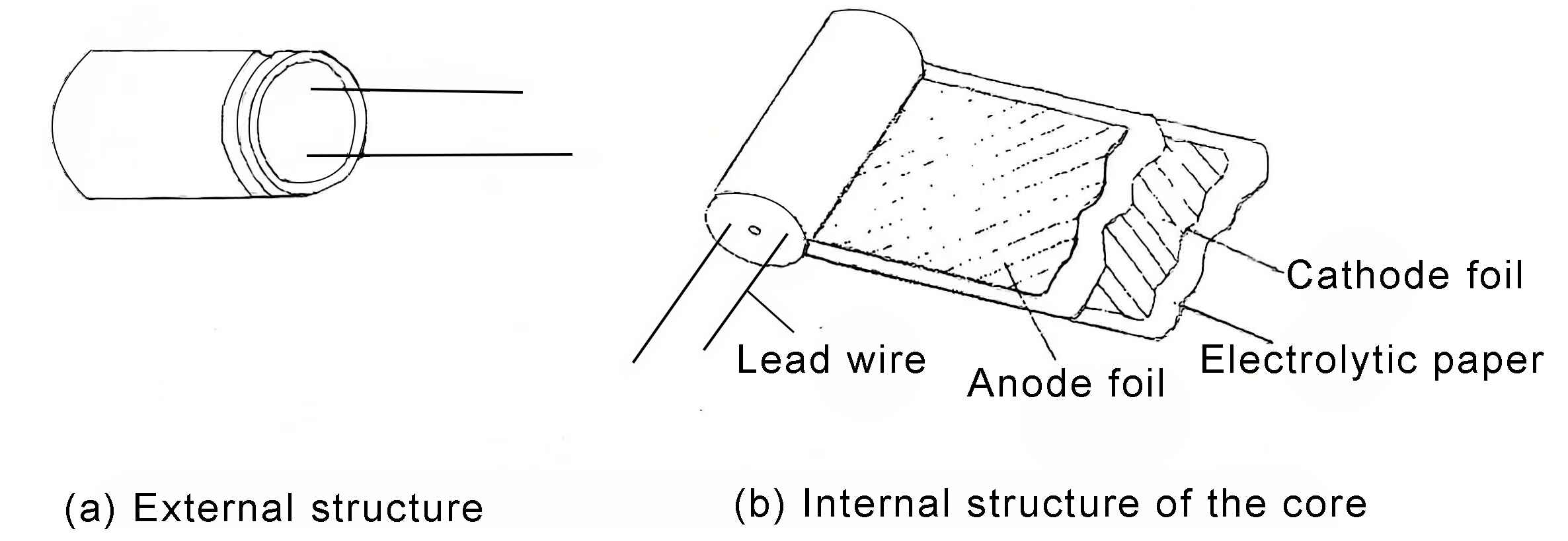
Figure 2 General-purpose aluminum electrolytic capacitor structure
3 Electrical performance characteristics
Compared with organic dielectric capacitors and inorganic dielectric capacitors, electrolytic capacitors have the following significant characteristics in electrical performance: (1) Large specific capacitance. That is, the capacitance per unit volume is very high. If V (cm3) represents the product volume and C (μF) represents the storage capacity, the ratio capacitance is:
![]() (3)
(3)
The ratio capacitance is larger, which means that under the same capacitance, the product has a smaller volume, which is conducive to the miniaturization of the product.
(2) The dielectric oxide film (Al2O3) can withstand extremely high working electric field strength. If U represents the working voltage and d represents the thickness of the dielectric oxide film, then its working electric field strength Ework is:
![]() (4)
(4)
The Ework of the Al2O3 dielectric film is generally about 600 kV/mm; while the electric field strength of the impregnated paper of the paper dielectric capacitor is about 200~300 kV/mm, which restricts the capacitor to only withstand 10~20 kV/mm; high-frequency ceramic dielectrics can only withstand 20~30kV/mm. Only with such a high working electric field strength can it provide sufficient and necessary prerequisites for miniaturization compared with other types of capacitors. The high working electric field strength of the dielectric oxide film of aluminum capacitors is related to the structure of its dense Al2O3 film.
(3) It has a self-healing effect. As the name implies, aluminum electrolytic capacitors rely on the negative ions (O2-) of oxygen provided by the working electrolyte during operation, which can automatically repair the defects and flaws in the Al2O3 film, so that the insulation performance of the parts can be repaired and improved at any time, improving the product’s voltage resistance characteristics.
In addition to the above advantages, aluminum electrolytic capacitor also have some disadvantages due to their own structural characteristics:
(1) The upper limit of the working voltage is subject to certain restrictions. For aluminum electrolytic capacitors, the maximum working voltage is about 500V
(2) It has unidirectional conductivity. The two electrodes of ordinary aluminum capacitors are polarized, and the anode should be connected to the positive pole in the circuit and the cathode to the negative pole of the circuit. They cannot be connected in reverse.
(3) The insulation quality is poor. The insulation quality of electrolytic capacitors is not measured by insulation resistance or time constant (r=CR) like ceramic dielectric and organic dielectric capacitors. Due to the poor insulation performance of electrolytic capacitors, it is generally expressed by current ILC. The reason for the low insulation quality is that its extremely thin dielectric oxide film is prepared by electrochemical methods, and its performance is easily affected by factors such as the purity of raw materials, process factors and process hygiene.
(4) The electrical performance of non-solid electrolyte aluminum electrolytic capacitor. Under long-term storage or long-term load operation, the working electrolyte will gradually dry up and deteriorate, resulting in a decrease in electrical performance. In particular, after long-term storage, the local insulation performance of the dielectric oxide film deteriorates. If the rated working voltage is suddenly applied, it is easy to cause damage to the capacitor, or even the explosion-proof valve to open and fail.
In addition, the loss tangent tgδ of aluminum electrolytic capacitor is large, and the temperature-frequency characteristics are also poor.
4 Electrical parameters and nominal series
Aluminum electrolytic capacitors usually use five parameters: nominal capacitance CR, loss tangent tgδ, leakage current ILC, rated working voltage UR and impedance Z to characterize their conventional electrical performance.
(1) Nominal capacitance and maximum allowable deviation of capacitance
Generally speaking, the so-called nominal capacitance refers to the capacitance value marked on the capacitor, which is the nominal value of the design capacity. There is a certain deviation between it and the actual capacitance of the manufactured capacitor, which is called the capacitance allowable deviation. The deviation is caused by the unevenness of raw materials and factors such as structural and process fluctuations.
The nominal capacitance value of aluminum electrolytic capacitors is based on the E6 series:
![]() (5)
(5)
Where: n=1,2,3,4,5,6, and is a positive integer.
According to the E6 series, the +20% error limit of any value in 1.0,1.5,2.2,3.3,4.7,6.8…10 must be connected to the -20% error limit of the previous value. This brings great convenience to production, that is, the production of a certain capacitance product must fall within a certain nominal capacitance range. The priority values of capacitance allowable deviation are shown in Table 1-1.
Table 1-1 Allowable deviation and text symbols
![]()
(2) Loss tangent Aluminum electrolytic capacitors used in pulsating circuits actually consume a small amount of active electrical power, which can be characterized by the loss tangent, which is the ratio of active power to reactive power of the capacitor’s electrical energy loss. For electrolytic capacitors, a series equivalent circuit is often used, as shown in Figure 3, then its loss tangent tgδ is:
![]() (6)
(6)
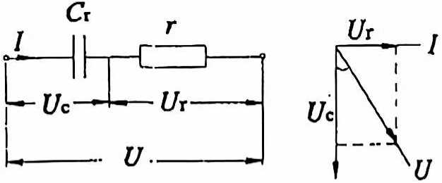
Figure 3 Equivalent series circuit and current-voltage vector diagram
(3) Leakage current The leakage current ILC is one of the five major electrical parameters of electrolytic capacitors and is used to characterize the insulation quality of electrolytic capacitors. It is closely related to the magnitude of the applied voltage, the ambient temperature and the length of the test time. Therefore, when specifying the leakage current value, the test time, the applied voltage U and the ambient temperature T must be indicated. The relationship between ILC and the test time (i.e., the applied voltage time), the applied voltage and the ambient temperature is shown in Figure 4.
For aluminum electrolytic capacitors, leakage current is usually expressed by the following formula:
![]() (7)
(7)
Figure 4 Relationship between capacitor current and test time, applied voltage and ambient temperature

Where: C—nominal capacitance of capacitor, μF;
U—rated working voltage, V;
K, M—constants.
The K value is called the hole current constant. Different types of electrolytic capacitors have different values, such as CD11 products, K=0.03: CD110 products, K=0.01: low current products, K=0.001~0.002.
For the M value, in addition to considering the leakage current of the oxide film itself, the influence of the leakage current on the capacitor surface should also be considered. The M value mainly depends on the product structure and the size of the CU value. For those with smaller CU values, the surface leakage current has a greater impact, and the M value is also added with a larger value accordingly; for those with larger CU values, the surface conduction current has a smaller impact, and the M value can be ignored, so the M value can be taken in the range of 0~20.
(4) Rated working voltage (UR)
It refers to the maximum DC voltage or maximum AC voltage effective value or pulse voltage peak value that can be continuously applied to the capacitor at any temperature between the lower limit category temperature and the rated temperature.
The rated voltage value series for electrolytic capacitors consists of the following values:
4.0, 6.3, 10, 16, 25, 35, 50, 63, 100, 160, 200, 250, 350, 400, 450, 500, and the unit is volt (V).

