1 Relationship between impedance, capacitance, loss tangent and equivalent series resistance
In terms of the characteristics of electrolytic capacitors, capacitance C, loss tangent tgδ and impedance Z or equivalent series resistance ESR are usually used to describe the electrical characteristics in pulsating circuits. In the equivalent circuit of the electrolytic capacitor introduced in the previous section, if the influence of the inherent inductance is considered, the inductance L of the electrolytic capacitor is generally not too large and will not exceed 100 nH (nanohenry), so the equivalent circuit of the electrolytic capacitor becomes as shown in Figure 1.

Figure 1 Equivalent circuit of electrolytic capacitor
In terms of the characteristics of electrolytic capacitors, the complex impedance at both ends of AB in this circuit is:
![]() (1)
(1)
The impedance modulus is:
![]()
When L is very small, ω2LC≪1, then:
![]() (2)
(2)
Therefore, the impedance of the capacitor will increase with the increase of the loss tangent.
From the series equivalent circuit of the electrolytic capacitor, we know that:
![]() (3)
(3)
Where the loss resistance r is composed of three parts: ① the equivalent series resistance rdielectric of the oxide film dielectric loss; ② the equivalent series resistance rliquid representing the working electrolyte; ③ rmetal representing the metal electrode, lead wire (sheet) and contact resistance. That is:
![]() (4)
(4)
r is called the equivalent series resistance, abbreviated as ESR (equivalent series resistance). Therefore
![]() (5)
(5)
2 The relationship between the characteristics of electrolytic capacitors and temperature characteristics
The main electrical parameters of electrolytic capacitors, C, tgδ and Z, have a very close dependence on the ambient temperature and frequency of use. The so-called temperature characteristics refer to the regularity of the change of C, tgδ and Z of the capacitor with the ambient temperature, while the frequency characteristics describe the regularity of the change of C, tgδ and Z of the capacitor with the frequency. The temperature-frequency characteristics of the capacitor not only reflect the inherent laws of the microscopic changes of the medium, but also are related to factors such as the properties of the electrolyte, the type of electrolytic paper and the structure of the capacitor. Of course, from the perspective of use, the smaller the change of temperature and frequency, the better.
2.1 Frequency characteristics
(1) Relationship between C and tgδ~ƒ
This can be explained from the formula (14), formula (15) and the dielectric dipole polarization theory in the previous article. In the low frequency band, the dielectric that constitutes the capacitor has a dipole polarization that can keep up with the change in the frequency of the external electric field, so the dielectric polarization rate is large, its polarization contribution to the capacitance is large, and the loss is small; in the high frequency band, it is the opposite of the above. As the frequency increases, the dielectric dipole polarization cannot keep up with the change in the external electric field, C will decrease, and tgδ will increase. This change relationship is shown in Figure 2.
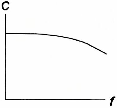
Figure 2 Capacitance and frequency curve
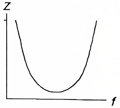
Figure 3 Impedance and frequency curve
(2) Relationship between Z and ƒ
Due to the influence of the inherent inductance of the electrolytic capacitor, the frequency characteristic curve of the impedance Z has a “U” shape, as shown in Figure 3. As shown in formula (1), in the low frequency band, the capacitive reactance plays a major role in the impedance. As the frequency increases, the impedance decreases. When the impedance reaches a certain minimum value, this frequency is the resonant frequency. In the high frequency band, the inductive reactance plays a major role. The inductance is formed when the current flows through the metal electrode, lead and metal casing. The following are different specifications of aluminum electrolytic capacitors 16 V470μF and 250V10μF, 47μF, 100μF, and their impedance frequency characteristics are shown in Figure 4.
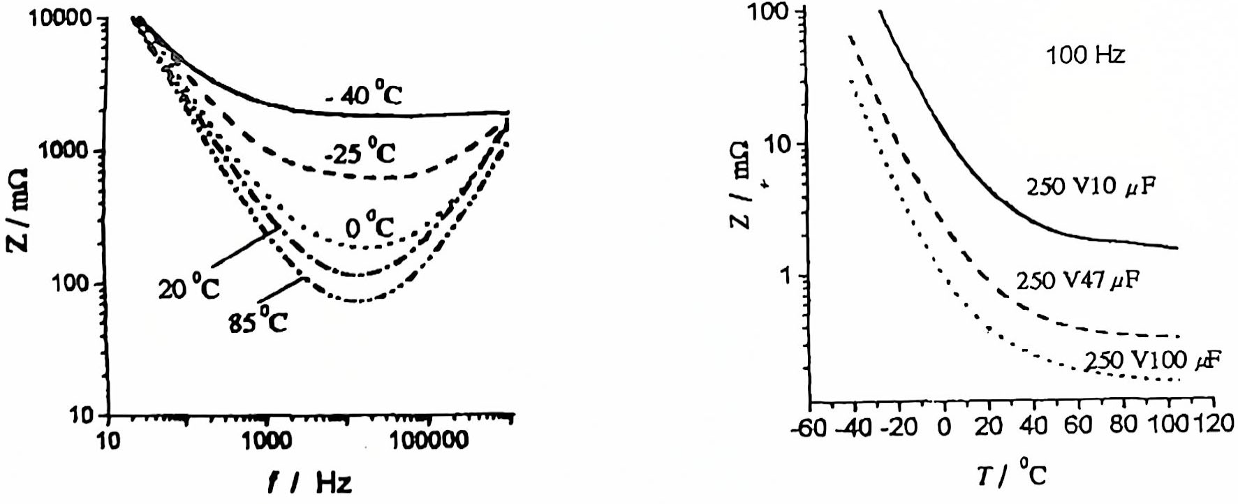
Figure 4 Impedance temperature frequency characteristics of typical aluminum electrolytic capacitors
2.2 Temperature characteristics
(1) Relationship between C、tgδ~T
The characteristics of electrolytic capacitors, such as capacitance C and loss tangent tanδ, are closely related to temperature changes. These relationships can be analyzed by formulas (14), (15) and dielectric polarization theory in the previous article.
At low temperatures, the electrolyte tends to “freeze”, and the resistance to the migration of its ions will increase greatly, and will increase as the temperature decreases, eventually leading to r→∞, then

When Cpaper≪C, then the formula (14) in the previous article becomes:
![]() (6)
(6)
Of course, from the formula (15) in the previous article, it can be seen that tgδ will increase as rliquid increases.
Similarly, at high temperatures, rpaper becomes smaller, tgδ decreases accordingly, and Cr→C.
(2) Z~T relationship
From formula (2), it is not difficult to see that as the temperature increases, tgδ decreases, and C also increases somewhat, but because tgδ decreases rapidly, the impedance Z will decrease at a faster rate as the ambient temperature increases, as shown in Figure 4.
3 Characteristics of electrolytic capacitors and leakage current and countermeasures to suppress leakage current rise
3.1 Source of current generation
The dielectric film of aluminum electrolytic capacitors is an Al2O3 film formed by electrochemical methods. Because of its extremely thin thickness, it is easily affected by factors such as raw material purity and manufacturing process. Therefore, there are always more or less tiny gaps, impurities and defects on the surface of the dielectric film, and lattice defects are easily formed in the crystal structure. In this way, after the voltage is applied to the aluminum electrolytic capacitor, electronic current and ion current are formed at the above-mentioned hidden dangers, among which electronic current is the main one. In addition, the influence of the leakage current on the surface of the capacitor should also be considered. It is related to the surface condition of the component (such as surface roughness and cleanliness) and the temperature and humidity of the environment. Therefore, leakage current is one of the most important electrical parameters of electrolytic capacitors, and it is also a direct indicator of the quality of electrolytic capacitors, whether the manufacturing process is appropriate, and whether the process is hygienic and civilized.
3.2 Expression of leakage current
From the equivalent circuit, it can be seen that the leakage current of aluminum electrolytic capacitor is the sum of the volume leakage current Iv of the oxide film medium and the leakage current Is through the surface, as shown in Figure 5. Its expression is:
![]() (7)
(7)
1)Volume leakage current Iv: due to the volume resistance Rv of the dielectric oxide film:
 (8)
(8)
Where: U-applied voltage, V;
K-corrosion coefficient;
S0-light foil geometric area, cm2;
γ-oxide film conductivity, (Ω·cm)-1;
p-oxide film resistivity, Ω·cm;
Uf-formation voltage, V;
a-formation constant, for aluminum anode foil a = 1.4×10⁻⁷cm/V.
Another expression:
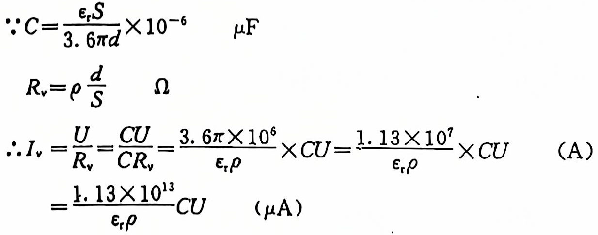
Let ![]() (9)
(9)
Assuming that the aluminum oxide film Ɛr=8~10, p=1013~1014Ω·cm, then
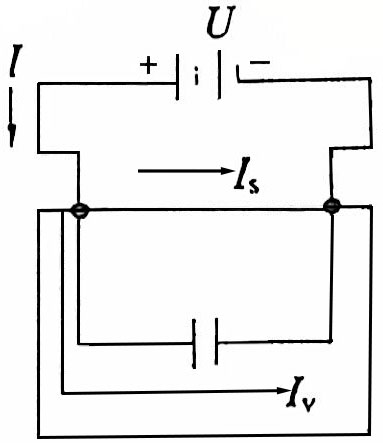
Figure 5 Schematic diagram of capacitor leakage current
The K value is about 0.01~0.1, which is just within the specified range of the K value of CD11 and (:D110 aluminum electrolytic capacitors, then
![]() (10)
(10)
According to the solid dielectric conductivity theory, Ohm’s law of ideal dielectrics can be applied to the range of breakdown electric field strength E=106~107V/cn. The characteristics of electrolytic capacitors under weak electric fields are characterized by the conductivity of the oxide film and the electric field strength. The relationship between E and γi tends to be flat, which conforms to Ohm’s law. Under a strong electric field, the conductivity behavior is ionic conductivity and electronic conductivity, and electronic conductivity occupies a dominant position.
(1) Ionic conductivity γi increases with the increase of E under a strong electric field, which can be considered to be caused by the relationship between ion mobility and E. Its conductivity γi is:
![]() (11)
(11)
(2) Electronic conductivity γe will have the following relationship (12) with the change of E under a strong electric field:
![]() (12)
(12)
In formulas (11) and (12), a, b, k1, k2, γo and temperature TTT are all known, and the electric field strength EEE and these factors jointly affect the characteristics of electrolytic capacitors.
2)Surface leakage current Is:
The size of Is is related to the physical properties of the sealing material used and the surface condition such as cleanliness, and it is difficult to quantitatively describe it with a certain formula.
In summary, the general expression of leakage current in engineering is:
![]() (13)
(13)
Generally speaking, when the CU value of the capacitor is relatively large, Is≪Iv, M=0. When the CU value is relatively small, Is has a relatively large impact on Iv and cannot be ignored. M can be 0~20.
3.3 Analysis of factors affecting current
(1) Influence of raw material purity
The raw materials of electrolytic capacitors, especially the materials that constitute the core, have a great influence on the current. It includes the purity of aluminum foil and lead wires, various chemical reagents used in the electrolyte, deionized water and impurity content in electrolytic paper, all of which have a great influence on the leakage current.
In the characteristics of electrolytic capacitors, when the purity of the anode aluminum foil of aluminum electrolytic capacitors is increased from 99.20% to 99.99%, its leakage current decreases significantly under the same conditions, especially at higher operating temperatures, the impact is more significant. As shown in Figure 6, improving the purity of aluminum foil is an effective way to extend the service life of electrolytic capacitors and reduce leakage current. The purity of the positive lead has the same effect. In addition, the content of fluoride ions and sulfate ions contained in other raw materials such as chemical reagents, electrolytic paper, rubber plugs, pure water, etc. is strictly required. Even if there is a very small amount of chloride in the working electrolyte, it will have a harmful effect on the product, because the presence of fluoride can not only damage the oxide film, but also cause the anode foil and lead to be corroded.
(2) The influence of the working electrolyte
The working electrolyte not only plays the role of the cathode of the electrolytic capacitor, but also needs to be able to provide O2- to the anode at any time to repair the damaged oxide film. If the electrolyte has poor ability to repair the oxide film and prevent the oxide film from deteriorating, the leakage current of the product will inevitably increase and the leakage current will rise.
In addition, the water in the electrolyte will cause the oxide film to form a hydrated oxide film AI2O3·nH2O (n=1~3), which will reduce the insulation performance of the dielectric film, which will also increase the leakage current.
(3) Influence of manufacturing process conditions
① Aging process conditions Aging process conditions mainly refer to the voltage and time, boost rate and constant current size of room temperature and high temperature aging. In addition to eliminating early defective products, the purpose of aging is more importantly to fully repair the damaged oxide film so that the oxide film (AI2O3) becomes a high-quality dielectric film. If the repair is not sufficient, it will cause the leakage current to increase or rebound, thereby affecting the characteristics of electrolytic capacitors.
② Process hygiene Uncivilized production and poor environmental hygiene conditions will cause the leakage current to increase. Because the dust in the air may contain conductive particles and the hand sweat contains a high concentration of C1–, these are also the reasons that seriously affect the leakage current of the product and make it larger.
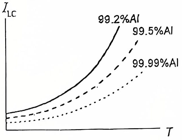
Figure 6 Relationship between aluminum foil purity and leakage current and temperature
(4) Influence of applied voltage size and time
The leakage current of the electrolytic capacitor increases with the increase of applied voltage. The rule is: when the external voltage value is lower than the rated working voltage UR of the capacitor, the leakage current increases slowly with the increase of the external voltage, and when the external voltage exceeds UR, the leakage current will rise sharply. The change rule is shown in Figure 7.
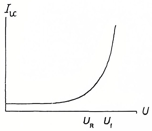
Figure 7 Relationship between current and applied voltage
This change can be explained as follows: when the applied voltage increases and the thickness of the dielectric oxide film remains unchanged, the electric field strength E applied to the oxide film will increase with the increase of voltage. The relationship between the electron current Ie, which is the main part of the leakage current, and the applied field strength E conforms to the sine hyperbola function:
![]() (14)
(14)
Where E is the applied electric field strength, a is a constant with an exponential relationship with temperature, and b is a constant.
When the electric field strength reaches a certain value, some weakly bound impurity ions in the dielectric crystal will participate in the conduction under the action of the strong electric field force, and as the voltage increases, the number of impurity ions participating in the conduction increases dramatically, thereby greatly increasing the leakage current.
The relationship between the leakage current of the electrolytic capacitor and the duration t of the applied voltage is shown in Figure 8
It can be seen from the figure that in the initial stage of the applied voltage, the leakage current decreases rapidly with the increase of the applied voltage duration, and finally reaches a certain stable value. The curve in Figure 8 can also be used to measure the quality of the product. The leakage current of a capacitor with good quality decreases quickly and has a small stable value. On the contrary, the leakage current of a capacitor with poor quality decreases quickly.
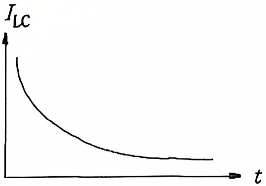
Figure 8 Relationship between leakage current and duration of applied voltage
(5) Effect of temperature
The leakage current increases exponentially with increasing temperature. This is because the migration capacity of impurity ions in the Al2O3 oxide film increases sharply with increasing temperature, which increases the ionic conductivity γi of the oxide film and thus increases the leakage current.
(6) Effect of storage time
After a period of time or long-term storage, the leakage current of the aluminum electrolytic capacitor increases, which is called leakage current rebound. This is an inherent shortcoming of the aluminum electrolytic capacitor itself, which is related to the fact that aluminum is amphoteric metal and aluminum and its compounds have poor ability to withstand the effects of chemical substances.
The longer the aluminum electrolytic capacitor is stored (shelved) and the higher the storage environment temperature, the greater the possibility of local destruction or damage to its dielectric oxide film. This is because the raw materials and manufacturing process inevitably bring in harmful impurities that cause local corrosion. In addition, harmful impurities such as C1– and SO42- form acids in the presence of aqueous solutions, which directly corrode the Al2O3 film and the aluminum foil. All of the above reasons lead to increased leakage current.
Therefore, products that have not been used for a long time or are in stock should be re-aged (also known as voltage treatment). The applied voltage should be slowly increased from low voltage to the rated working voltage or 1.25 times the rated voltage (room temperature), and the process is the same as the aging process. The impact of storage is particularly serious on high-voltage and large-capacity products, and sufficient attention must be paid.
3.4 Countermeasures to suppress leakage current rebound
The leakage current rebound is relatively complex and involves many issues. It is necessary to grasp the characteristics of electrolytic capacitors in the analysis of many factors to help solve the problem more effectively. The following countermeasures can usually be taken:
(1) Select high-quality working electrolyte.
(2) Select high-quality anode foil, or select anode foil with a high voltage Uf and a small corrosion coefficient k. This principle can be analyzed from formula (8).
(3) Properly extend the aging time and change the aging method, such as pulse aging or intermittent aging.
(4) Strengthen raw material inspection. Strictly control the content of C1– and SO42-, preferably below 0.5 mg/L.
(5) Promote civilized production. Purify the production environment and prevent hand sweat from contaminating the core before assembly.
(6) Use chemical lead for positive lead, especially for small-capacity capacitors.
(7) Appropriately tighten the leakage current factory control index.

