Electrolytic capacitors are often used in electronic circuits for filtering, bypassing, coupling, and frequency division. In these applications, the voltage applied to the electrolytic capacitor is a DC voltage with an AC component voltage of different frequencies superimposed on it, which is called a pulsating voltage (also called a ripple voltage). In this case, the AC current flowing through the aluminum electrolytic capacitor is called the electrolytic capacitor ripple current. The size of the electrolytic capacitor ripple current directly affects the performance and life of the capacitor, so when designing and using electrolytic capacitors, special attention should be paid to the characteristics and effects of the ripple current.
1 Analysis of the electrolytic capacitor ripple current of the on the ability to withstand ripple voltage
Since the electrolytic capacitor is polar, when it is used in a pulsating circuit, the instantaneous AC voltage peak may put the capacitor in a reverse state, so the ability of the electrolytic capacitor to withstand reverse voltage must be considered.
Assuming that the AC voltage of the electrolytic capacitor in the pulsating circuit is a sine wave, then U~=Umsinωt, superimposed on the DC voltage U–, its waveform is shown in Figure 1.
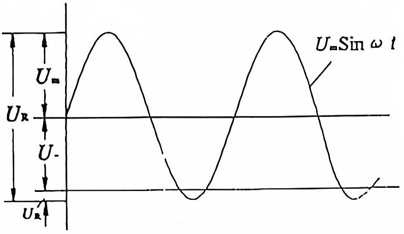
Figure 1 Voltage waveform of electrolytic capacitor in pulsating circuit
For aluminum electrolytic capacitors, the ability to withstand reverse voltage is mainly determined by the thickness of the cathode foil oxide film. For low-voltage capacitors, the natural oxide film thickness on the cathode foil is relatively thicker than the anodic oxide film, so it can withstand a certain value of reverse voltage. The current national standard stipulates that 6.3~160V products can withstand a reverse voltage of 1V. For high-voltage capacitors, this film on the cathode is too thin. In order to improve its ability to withstand reverse voltage, or for products that require reverse voltage resistance, the cathode foil can be specially formed so that the oxide film on the cathode foil reaches a certain thickness, but this is at the expense of capacity or increased volume.
In addition, when electrolytic capacitors are used in pulsating circuits, the following should be considered:
(1) The sum of the peak value U~ of the AC voltage component of the pulsating voltage and the DC voltage component U– should not exceed the rated working voltage UR value, that is,
![]()
(2) The ripple current through the electrolytic capacitor should not exceed the value specified in the standard.
2 Calculation of allowable ripple current and allowable temperature rise
When an electrolytic capacitor works in a pulsating circuit, the allowable ripple current it bears should be considered from two aspects: one is the temperature rise caused by heating, and the other is the ability to withstand reverse voltage.
(1) Considering the temperature rise caused by heating
When the electrolytic capacitor ripple current of the flows through the capacitor, the capacitor itself has losses and causes active power loss, resulting in heating and temperature rise. The following will calculate the allowable ripple current value and allowable temperature rise so that the electrolytic capacitor can be correctly selected and can also be used as a basis for capacitor design. For the whole machine circuit designer, it is extremely important to correctly set and select electrolytic capacitors.
When the electrolytic capacitor passes the ripple current, the active power loss Pactive is:
![]() (1)
(1)
Where: a-heat dissipation coefficient, W/(cm2·℃), generally a=1×10⁻³~2×10⁻³.
∆t-The maximum allowable temperature rise of the product at the extreme temperature, ℃.
S-Heat dissipation area, that is, the surface area of the product, cm2.
If the effect of heat dissipation on the rubber plug end face of the capacitor is ignored, then
![]() (2)
(2)
Where D and H are the outer diameter and height of the product, respectively, in cm.
On the other hand, the active power Pactive of the capacitor can be calculated from the equivalent circuit:
![]() (3)
(3)
Where U~ is the effective value of the AC component at a certain frequency, that is, the effective value of the ripple voltage
![]() (4)
(4)
When a=2×10⁻³,
![]() (5)
(5)
Active power Pactive power can also be used to characterize the product’s allowable pulsating load capacity by the size of the electrolytic capacitor ripple current:
 (6)
(6)
In the formula, the unit ƒ is Hz, C is μF, S is cm2, and ∆t is ℃
From the above formula (6), it can be seen that:
(1) The allowable ripple current is proportional to the frequency ƒ of the applied pulsating voltage, the capacitance C, the heat dissipation area S, the allowable temperature rise ∆t and the square root of the heat dissipation coefficient a.
(2) I~ is inversely proportional to the square root of tgδ, that is, the larger the tgδ of the product, the smaller the allowable ripple current it can withstand.
The maximum allowable temperature rise ∆t is calculated from formula (6):
![]() (7)
(7)
In the formula, the temperature rise ∆t=T2-T1. T1 is the temperature before the test, T2 is the temperature that causes the temperature rise after the ripple current is superimposed, and the highest ambient temperature that can work continuously at this temperature.
The △t value varies depending on the technical level of the manufacturer. Generally speaking, 5℃ is taken for 85℃ products, and 2~3℃ can be taken for 105℃ products.
Example 1: Try to calculate the maximum allowable temperature rise value of CD110 type 16V220μF product under the specified allowable ripple current. Solution: According to the national standard value of CD110 type aluminum electrolytic capacitor, tgδ=0.16, ripple current 180 mA, and outer size φ10 mm×12 mm, then its heat dissipation area S≈3.768 cm2 (top area is negligible).
Assume a=2×10⁻³ W/(cm2·℃), ƒ=100 Hz, and substitute these relevant parameters into formula (7) to obtain
![]()
Example 2: Based on the CD11 type 25 V100 μF product, try to calculate its allowable ripple current value under the allowable temperature rise of 5℃. Solution: According to the national standard value of CD11 aluminum electrolytic capacitor, tgδ=0.25, the outer size is φ8 mm×12 mm, then its heat dissipation area S=πDH≈3.014 cm2 (ignore the heat dissipation at the bottom and top of the aluminum shell), ƒ=100 Hz, substitute these parameters into formula (6) to get:
![]()
The ripple current specified in the current CD11 aluminum electrolytic capacitor standard is calculated based on the temperature rise of 5℃.
3 Correction coefficient of electrolytic capacitor ripple current
In the formula (6) for calculating the allowable ripple current, if the frequency, waveform and ambient temperature of the applied voltage (or current) are different, the allowable ripple current will be different. Therefore, the frequency correction coefficient Kf, waveform correction coefficient Kw and temperature correction coefficient KT must be introduced to make the severity equal or equivalent after correction.
3.1. Frequency correction coefficient Kf
According to the capacitor heating power Pactive = I2~r, assume that the allowable ripple current is If1 when the frequency is ƒ1, and the equivalent series resistance is rf1, and the allowable ripple current is If2 and the equivalent series resistance is rf2 when the frequency is ƒ2. If the severity of the two is the same at two different frequencies, the heating power of the two is equal. Then:
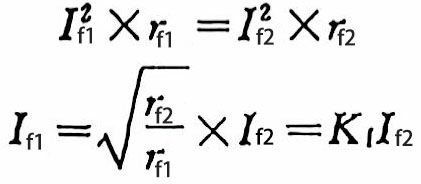 (8)
(8)
Frequency correction coefficient:
![]() (9)
(9)
In addition, another expression of Kƒ value can be derived from formula (6):
 (10)
(10)
Example: According to the current national standard, the rated ripple current is specified at 85℃:100Hz. If the ripple current frequency output by the experimental instrument is 50 Hz, how should the electrolytic capacitor ripple current of the aluminum be corrected?
Solution: At ƒ1=50 Hz, the capacitance is C1 and the loss tangent is tgδ1. At ƒ2=100 Hz, the capacitance is C2 and the loss tangent is tgδ2.
Assuming that C1×tgδ2=C2×tgδ1, according to formula (10), we have:
![]()
The national standard has stipulated that “if the rated ripple current value of 50 Hz is required, the rated ripple current value of 100 Hz can be multiplied by 0.7”, and this value is obtained based on this principle.
In fact, C1×tgδ2>C2×tgδ1, which means that the actual frequency correction coefficient Kf is larger than 0.7, and the higher the frequency, the greater the C1×tgδ2 will be. C2×tgδ1 value.
3.2. Temperature correction coefficient KT
The ripple current value specified in the current national standard is the ripple current value under the upper limit temperature of 85 ℃. If the ambient temperature is higher than 85 ℃, the ripple current value must be reduced. On the contrary, if the ambient temperature is lower than 85 ℃, the ripple current value can be increased to make it equivalent to the severity under 85 ℃ conditions. There is a temperature correction factor KT problem, which can be expressed as follows:
![]() (11)
(11)
Where: IT1-allowable ripple current value when temperature is T1;
IT2-allowable ripple current value when temperature is T2.
3.3. Waveform correction factor Kw
Generally speaking, ripple current refers to the effective value of sinusoidal current. If the waveform of the ripple current is a half-sine wave, a pulse wave, or an intermittent triangle wave, it should be converted according to the effective value calculation formula shown in Table 1.
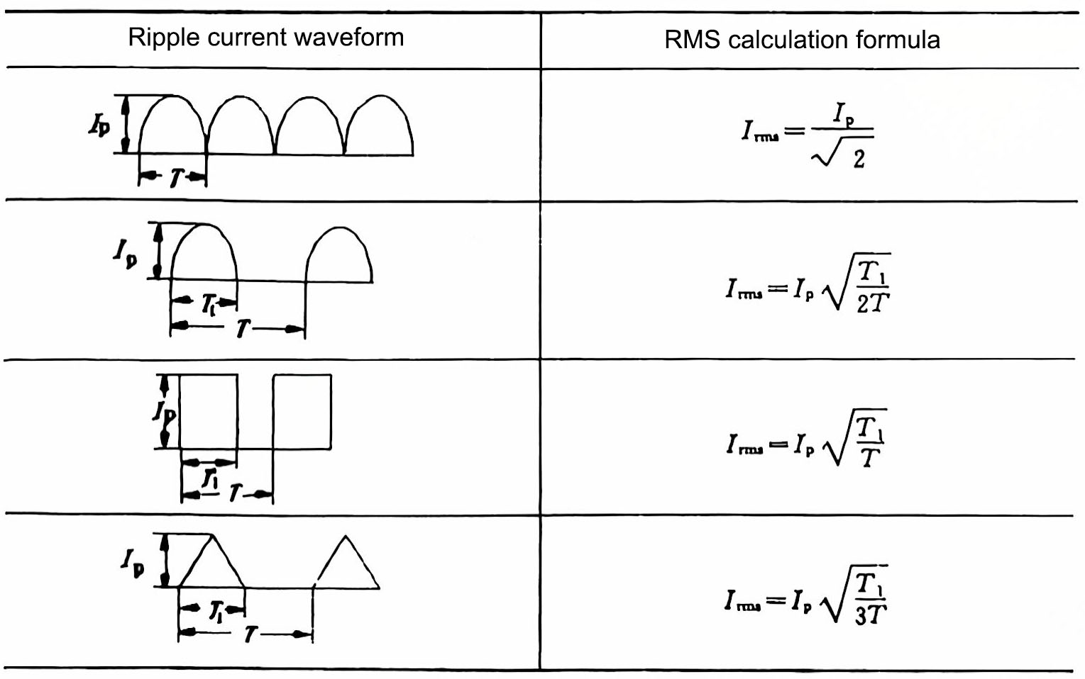
Table 1 Relationship between ripple current and effective value of different waveforms
Irms in the table is the effective value of current.
It should be pointed out that the above ripple current correction factor is obtained through theoretical calculation, but many manufacturers currently determine the correction factor of the product through experimental results. Because the correction factor is related to many factors such as the quality of the raw materials used, the characteristics of the working electrolyte, and the level of manufacturing technology, the correction factors of different manufacturers are not exactly the same. In addition, the size of the correction factor can also be used to measure the technical level of the manufacturer.

